PN16

BURKERT 20079457 Type 6281 servo-assisted 2/2-way solenoid valve. Features 25mm orifice, brass body, NBR seal, G1 thread, and 230V operation for 0.2-16 bar.
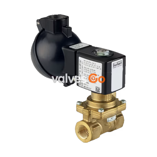
BURKERT 20079457 Type 6281 is a servo-assisted 2/2-way diaphragm valve. A minimum differential pressure is always required for the valve to function. The standard brass body meets European drinking water requirements. The valve features a vibration-resistant, centrally screwed coil system and a damped design for quiet closing.
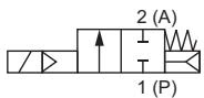
Circuit function A (CF A) 2/2-way solenoid valve, servo-controlled, normally closed.
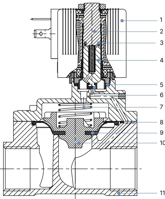
| No. | Element | Material |
|---|---|---|
| 1 | Coil | Polyamide or epoxy |
| 2 | Stopper | Stainless steel 1.4113 |
| 3 | Shading ring | Cu (brass variant) / Ag (stainless steel variant) |
| 4 | Magnetic core | Stainless steel 1.4113 |
| 5 | O-ring | NBR, FKM, EPDM |
| 6 | Core seal | NBR, FKM, EPDM |
| 7 | Spring | Stainless steel 1.4310 |
| 8 | O-ring | NBR, FKM, EPDM |
| 9 | Diaphragm | NBR, FKM, EPDM |
| 10 | Diaphragm holder | PPSGF40, DN 50: brass and stainless steel |
| 11 | Valve body | Brass acc. to DIN EN 50930-6 or stainless steel 1.4408 (CF8M) |
Standard Threaded Variant
INFO
Dimensions in mm. The dimensions F1 and G1 apply to G thread.
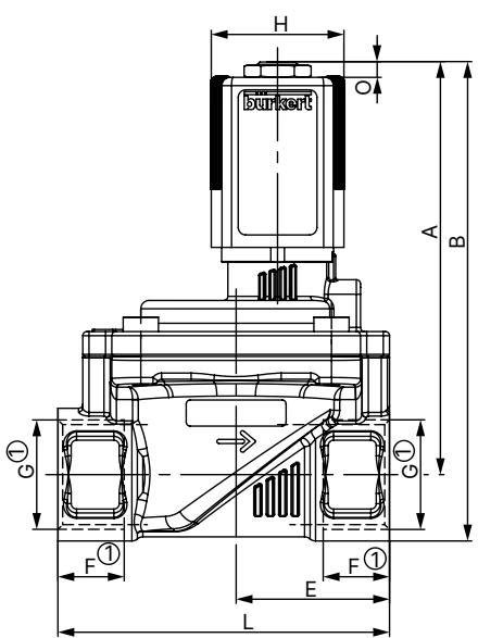
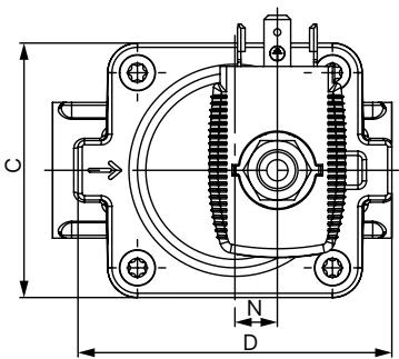
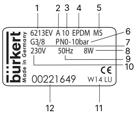
| 1 Type | 2 Circuit function |
|---|---|
| 3 Orifice | 4 Sealing material |
| 5 Body material | 6 PN |
| 7 Connection type | 8 Power |
| 9 Frequency | 10 Voltage |
| 11 Manufacture code | 12 Article number |
Risk of injury from high pressure
Before loosening lines or valves, switch off the pressure and vent the lines.
Risk of injury from electric shock
Before reaching into the device or the system, switch off the power supply and secure it against reactivation. Observe the applicable accident prevention and safety regulations for electrical devices.
Before installation:
Installation:
Overheating, risk of fire
Connecting the solenoid without a pre-installed valve will cause overheating and destroy the solenoid. Only connect the solenoid after the valve has been installed.
Solenoid installation approach:
Troubleshooting: If the valve does not actuate, check for a short circuit or interrupted solenoid, core contamination, or operating pressure outside the permitted range. If the valve does not close, check for interior contamination, a blocked control bore in the diaphragm, or if the valve was opened by manual override.
Explore similar products in our catalog