PN16

BURKERT 20081212 is a Type 8640 REV3 pneumatic valve island configured with 16.5 mm station width, G 3/8 supply, D8 push-in ports, 1 to 10 bar pressure, IP20 protection, and single wiring connection for 3/2-way valves.
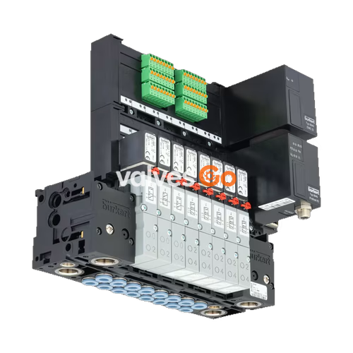
BURKERT 20081212 (Type 8640) is a modular pneumatic valve island configured with a 16.5 mm station width, G 3/8 pneumatic supply connections, bottom-oriented D8 push-in working connections, and single wiring parallel connection. Engineered for direct standard DIN rail mounting (EN 50022), this revision 3 (REV3) valve island operates with mixed valve populations including 3/2-way pilot functionalities across a nominal pressure range of 1.0 to 10.0 bar and medium temperatures from 0 °C to +50 °C.

Type 8640 combines pneumatic connection modules and electrical termination blocks on a continuous DIN-rail carrier. The body and intermediate modules are molded from high-grade polyamide (PA) using integrated snap connections for mechanical assembly without individual mounting brackets.
Revision 3 (REV3) Identification
Revision 3 (REV3) modules feature blue release rings on the push-in tube fittings and an optimized wavy pneumatic channel arrangement inside the basic module bodies. Compared to previous revisions with black release rings, REV3 modules reduce flow resistance and minimize pressure loss across the manifold.
| Technical Parameter | Specification Value |
|---|---|
| Article Number | 20081212 |
| Device Type | 8640 |
| Hardware Generation | Revision 3 (REV3) |
| Width per Station | 16.5 mm |
| Valve Configuration | Mixed valve population (3/2-way valve function) |
| Supply Port 1 (P), Exhaust Ports 3 (R), 5 (S) | G 3/8 female thread |
| Working Ports 2 (A), 4 (B) | Push-in coupling ∅ 8 mm (D8) |
| Working Port Position | Bottom (pneumatic module) |
| Nominal Operating Pressure Range | 1.0 bar to 10.0 bar (overpressure to atmospheric) |
| Medium Temperature Range | 0 °C to +50 °C |
| Ambient Temperature Range | 0 °C to +55 °C |
| Storage Temperature Range | -20 °C to +60 °C |
| Operating Medium | Compressed dry air, neutral gases (ISO 8573-1: 2010, Class 7.4.4; 5 μm filtration recommended) |
| Operating Voltage | 24 V DC (±10% tolerance, permissible residual ripple 1 Vss) |
| Electrical Protection Class | Class III according to VDE 0580 |
| Ingress Protection Rating | IP20 (IP65 achievable when installed inside closed control cabinets) |
| Digital Inputs | 0 PCE |
| Pressure Sensors | None |
| Intermediate Supply Feed Quantity | 0 PCE |
| Pneumatic HotSwap in 1 (P) | No |
| Integrated Non-Return Check Valves | No |
| Installation Interface | Standard DIN rail EN 50022 (35 x 7.5 mm or 35 x 15 mm) |
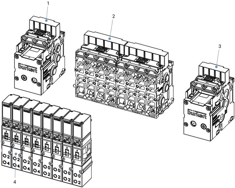
Pneumatic assembly for 16 mm station width configurations consists of four primary module elements:
Article 20081212 uses a collective connection module with screw-type terminals designed for single-conductor parallel wiring rather than a digital fieldbus node. Each valve position is controlled through discrete individual conductors with looped-through common ground potential. The collective connection module supports up to 24 valve outputs with a total current capacity of 3 A across the terminal block.
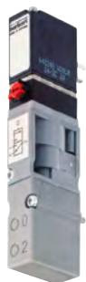
Type 8640 REV3 manifolds with 16.5 mm station width interface with Type 6526 (3/2-way) and Type 6527 (5/2-way) solenoid valves. Each valve consists of a pneumatic body combined with a Type 6106 rocker pilot actuator. Rocker movement eliminates sliding friction, allowing continuous operation (100% duty cycle) without base lubrication.
| Valve Model | Circuit Function | Orifice DN | QNn Air Flow | Operating Pressure Range | Coil Power | Article Number |
|---|---|---|---|---|---|---|
| Type 6526 | 3/2-way NC (Circuit Function C) | 6.0 mm | 700 l/min | 1.0 to 10.0 bar (aux. pilot air) | 2 W (24 V DC) | 156842 |
| Type 6526 | 3/2-way NC (Circuit Function C) | 6.0 mm | 700 l/min | 2.0 to 10.0 bar | 2 W (24 V DC) | 156318 |
| Type 6526 | 3/2-way NC (Circuit Function C) | 6.0 mm | 700 l/min | 2.0 to 8.0 bar | 1 W (24 V DC) | 156840 |
| Type 6526 | 3/2-way NO (Circuit Function D) | 6.0 mm | 700 l/min | 1.0 to 10.0 bar (aux. pilot air) | 2 W (24 V DC) | 163029 |
| Type 6526 | 3/2-way NO (Circuit Function D) | 6.0 mm | 700 l/min | 2.0 to 10.0 bar | 2 W (24 V DC) | 156320 |
| Type 6526 | 3/2-way NO (Circuit Function D) | 6.0 mm | 700 l/min | 2.0 to 8.0 bar | 1 W (24 V DC) | 156841 |
| Type 6527 | 5/2-way (Circuit Function H) | 6.0 mm | 700 l/min | 1.0 to 10.0 bar (aux. pilot air) | 2 W (24 V DC) | 156828 |
| Type 6527 | 5/2-way (Circuit Function H) | 6.0 mm | 700 l/min | 2.0 to 10.0 bar | 2 W (24 V DC) | 156337 |
| Type 6527 | 5/2-way (Circuit Function H) | 6.0 mm | 700 l/min | 2.0 to 8.0 bar | 1 W (24 V DC) | 156827 |
All Type 6526 and Type 6527 valves include a lockable manual override as standard. In electrical operation, manual overrides must remain in the de-energized default position.
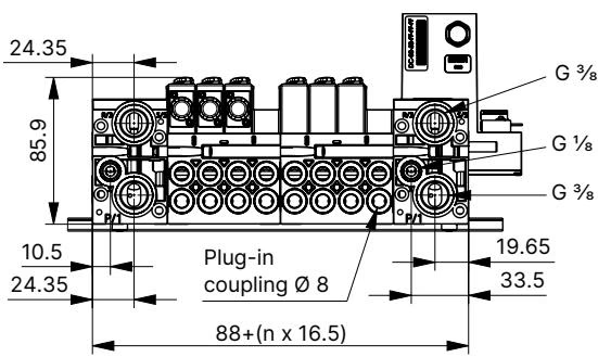
Manifold dimensions scale in increments of 16.5 mm per station. The overall length is governed by the number of basic 4-fold pneumatic units plus the left and right supply modules (G 3/8 threaded ports). Working connections exit from the bottom face of the pneumatic modules to enable direct downward tubing runs in control enclosures.
Operating Pressure and Pressurization Sequence
Ensure that the pressure supply provides at least 2.0 bar at the valve inlet before switching valves. When powering up the system, apply pneumatic pressure to the island before switching pilot valves. Pressurizing valves in an energized state can cause delays or exhaust blow-off.
Connect supply and exhaust channels to the G 3/8 threaded ports on the end modules. For the D8 push-in working connections, verify tubing conforms to DIN 73378 and ISO 14743:2020:
Retention Force and Tensile Verification
According to DIN ISO 14743:2020, properly seated 8 mm push-in connections must withstand a minimum tensile pull-off force of 170 N for polyamide (PA) hose and 150 N for polyurethane (PU) hose. If flexible PU hoses exhibit leakage under mechanical movement, install internal support sleeves (article 20099400).
| Element Description | Specification / Model | Article Number |
|---|---|---|
| Replacement Valve Type 6526 | 3/2 NC, DN 6, 2 W, 2.0-10 bar, 24 V DC | 156318 |
| Replacement Valve Type 6527 | 5/2, DN 6, 2 W, 2.0-10 bar, 24 V DC | 156337 |
| Base Unit REV3 16 mm (4-fold) | 4-station base module, D8 ports, FM17 interface | 20042790 |
| Base Unit REV3 16 mm (4-fold RSV) | 4-station base module, D8 ports, check valves | 20042792 |
| Left Supply Unit 16 mm | G 3/8 pneumatic feed, left termination | 20042793 |
| Right Supply Unit 16 mm | G 3/8 pneumatic feed, right termination | 20042796 |
| Valve Seal Kit FM17 | Pack of 12 replacement seals for Type 6526 / 6527 | 20016307 |
| Module Seal Kit MP17 | Pack of 4 inter-module seals for 16 mm REV3 | 20016310 |
| Valve Slot Cover Plate | Blanking plate for unused 16.5 mm valve positions | 653765 |
| Electrical Terminal Cover | Blanking cover for electrical base connection | 657519 |
| Fault Observed | Possible Cause | Corrective Action |
|---|---|---|
| Valves fail to switch | Operating voltage missing or below 24 V DC (±10%) | Check electrical connections at the collective terminal; verify supply voltage matches nameplate ratings. |
| Valves fail to switch | Manual override engaged in locked position | Rotate manual override 90° counter-clockwise back to the de-energized zero position. |
| Valves fail to switch | Insufficient or absent pneumatic supply | Verify supply pressure meets minimum threshold (≥ 2.0 bar); check upstream regulators, filters, and isolation valves. |
| Delayed switching or blow-off at exhaust ports | Supply pressure drops during switching | Verify supply line volume and receiver capacity; ensure minimum operating pressure ≥ 2.0 bar is maintained under flow. |
| Delayed switching or blow-off at exhaust ports | Valve switched prior to system pressurization | Pressurize the valve manifold before energizing pilot solenoid coils. |
| Delayed switching or blow-off at exhaust ports | Exhaust port 3 or 5 restricted by undersized or clogged silencer | Install higher-flow silencers or clean existing silencers to prevent backpressure buildup. |
| Delayed switching or blow-off at exhaust ports | Particle contamination in valve chamber | Blow out exhaust passages with pulsed pressure; replace affected pilot or pneumatic valve if seat is damaged. |
| Air leakage between modular blocks | Missing or pinched O-rings between modules | Disassemble adjacent modules, inspect seal seats, and install undamaged MP17 module seals. |
| Air leakage at valve seating interface | Missing or misaligned flat seal beneath valve body | Loosen M3 fastening screws, inspect FM17 profile seal, realign, and torque to 0.6 ±0.1 Nm. |
Explore similar products in our catalog