PN16

BURKERT 20081390 Type 8640 modular valve island for pneumatics. Features 11 mm width per station, 8x 5/2 valve function H, G 1/4 pressure port, and IP20 multi-pole connection.
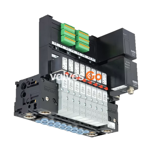
BURKERT 20081390 Type 8640 modular valve island for pneumatics is designed to solve diverse and complex control problems due to its systematic modular construction and combination of pneumatic and electrical interfaces. By putting together a row of pneumatic modules with different numbers of valves, 2 to 24 valve functionalities may be realized on one valve unit. The 20081390 configuration features an 11 mm width per station, 8x 5/2-way valve function H, a G 1/4 pressure port, and a multi-pole electrical connection.
Bodies and connection modules are made of high-quality plastic (polyamide) and are easy to assemble by means of the built-in snap connectors.

| Property | Value |
|---|---|
| Width per station | 11 mm |
| Number of valve slots | 24 (Max. 12 for impulse and double valves) |
| Body material | PA (polyamide) |
| Seal material | FKM, NBR and PUR |
| Pressure range | 2.5...10 bar |
| Medium temperature | 0 °C...+ 50 °C |
| Ambient temperature | 0 °C...+ 55 °C |
| Operating medium | Oil-free or lubricated compressed dry air, neutral gases (5 μm filter recommended) |
| Compressed air quality | ISO 8573-1: 2010, Class 7.4.4 |
| Degree of protection | IP20 (IP65 in closed control cabinets) |
| Working port | D6 |
| Air supply connection 1 (P), 3 (R), 5 (S) | G 1/4 |
| Communication interface | Multi-pole (Sub D 25-pin) |
| Installation position | As required, preferably with actuator upright |
The 20081390 configuration is equipped with 8x 5/2-way valve function H.
| Symbol | Description |
|---|---|
| Circuit function H (CF H) | 5/2-way solenoid valve Servo-controlled, with manual override Pressure applied via port (1), therefore one of the two ports (2) or (4) is under pressure. |
| Module | Description |
|---|---|
Multi-pin module Valve outputs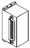 | Max. 24 valves Degree of protection IP20 Electrical connection plug D-Sub (25-pin) |
Pneumatics 11 mm width per station
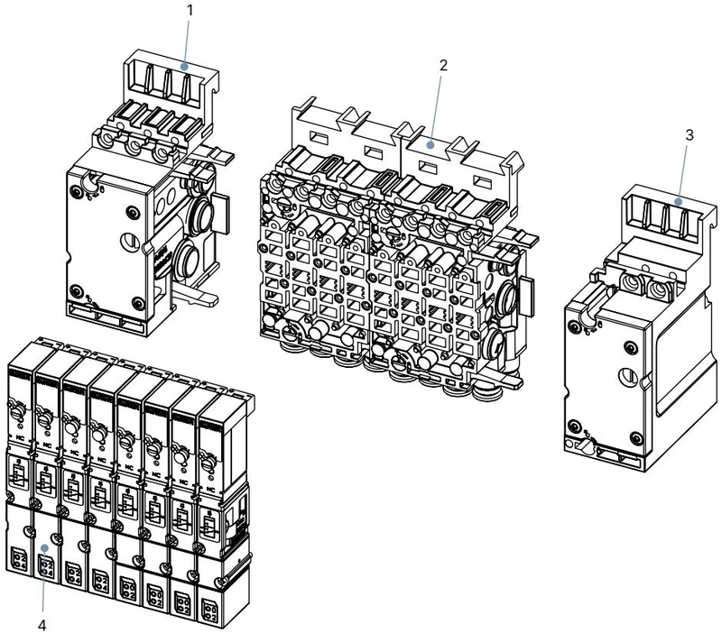
| No. | Element |
|---|---|
| 1 | Pneumatic connection module, left |
| 2 | Basic pneumatic modules |
| 3 | Pneumatic connection module, right |
| 4 | Valves (for example 5/2-way) |
Pneumatics 11 mm width per station
INFO
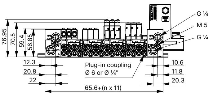
Dimensions in mm, unless otherwise stated.
DANGER!
Risk of injury due to high pressure and escaping medium.
Risk of injury due to electric shock.
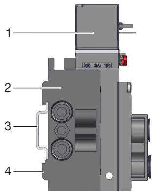
Standard rail installation
Wall installation
Recommended action for push-in connectors
Tightening torques for port connections
| Port size | Marking/function | Recommended tightening torque [Nm] | Maximum tightening torque [Nm] |
|---|---|---|---|
| G1/4 | P, R/S connection | 4...7 | 20 |
| G1/8 | P, R/S connection A/B valve outlets | 3...6 | 7 |
Explore similar products in our catalog