

PN16

BURKERT 20083344 (Type 6281) is an ATEX/IECEx-certified servo-assisted 2/2-way solenoid valve with G 3/8 stainless steel body, FKM seals, 24 V AC/DC operation, PN16 rating, and 3 m molded cable for hazardous locations.
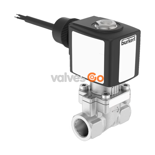
BURKERT 20083344 (Type 6281) is a servo-assisted 2/2-way diaphragm solenoid valve engineered for fluid shut-off and dosing in hazardous operating environments. Configured in circuit function A (normally closed), the valve operates with a minimum differential pressure of 0.2 bar and provides positive shut-off up to 16 bar. The assembly features an investment-cast stainless steel 1.4408 (CF8M) valve body with G 3/8 internal thread connections, a 10 mm main orifice, FKM seals, and an explosion-proof coil system rated for 24 V AC/DC operation.
Designed for rigorous chemical, process, and gaseous oxygen installations, this specific part number is certified to ATEX and IECEx standards under encapsulation protection type Ex mb. It is degreased and free of oil and grease in accordance with DIS 1000020797, making it suitable for gaseous oxygen service (code NL02). Electrical connection is established via a factory-molded 3000 mm crosslinked PO copolymer cable, ensuring an IP65 degree of protection without requiring separate enclosure field wiring.
Type 6281 requires an operating differential pressure across the diaphragm to open and close. Full cross-sectional opening occurs once the differential pressure reaches 0.5 bar.
| Technical Attribute | Specification |
|---|---|
| Product Type | 6281 (Generation EV) |
| Article Number | 20083344 |
| Circuit Function | A (2/2-way, normally closed) |
| Port Connection | G 3/8 internal thread |
| Main Valve Orifice (DN) | 10 mm (3/8") |
| Pilot Control Orifice | 1.2 mm |
| Flow Factor Kv (Water) | 1.9 m³/h |
| Flow Rate QNn (Gas) | 2050 l/min |
| Nominal Pressure Rating | PN 16 (0.2 to 16.0 bar) |
| Operating Voltage | 24 V AC/DC (50/60 Hz, tolerance ±10%) |
| Nominal Power (ATEX AC/DC) | 7 W (coil width 32 mm) |
| Duty Cycle | 100% ED continuous operation |
| Opening Time | 0.1 to 1.5 s |
| Closing Time | 0.2 to 4.0 s |
| Medium Temperature | 0 °C to +60 °C (datasheet rating up to +90 °C for FKM in ATEX cable models) |
| Ambient Temperature | -30 °C to +55 °C |
| Ingress Protection | IP65 (with properly sealed connection) |
| Flow Direction | Above seat (marked by body flow arrow) |
| Manual Override | None |
Differential Pressure Requirement
Servo-assisted diaphragm valves require a minimum differential pressure between the inlet and outlet ports of at least 0.2 bar to actuate. A differential pressure of 0.5 bar is required to fully open the 10 mm orifice cross-section.
BURKERT 20083344 carries dual ATEX and IECEx certifications for use in gas and dust explosion-hazard atmospheres:
Temperature Class Medium Limitation
According to the operating limits for explosion-protected valves, the maximum medium temperature must never exceed the permitted temperature class minus 5 K. For temperature class T4 (+135 °C), the process medium limit is +130 °C, subject to the +60 °C / +90 °C maximum rating of the selected FKM diaphragm material.
In addition to hazardous location certifications, the unit complies with manufacturer declarations for gaseous oxygen applications (code NL02) and has been cleaned free of combustible oils and lubricants according to DIS 1000020797.
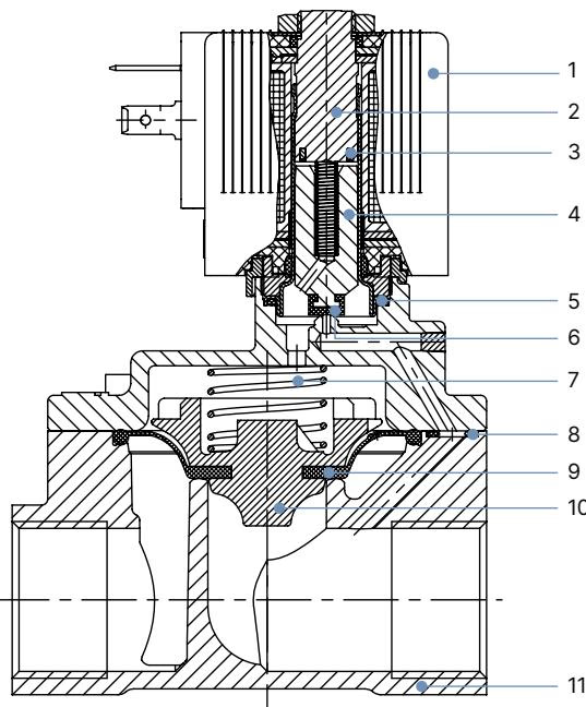
| Item No. | Element | Material |
|---|---|---|
| 1 | Solenoid Coil | Epoxy encapsulation (with FKM seals) |
| 2 | Stopper | Stainless steel 1.4113 |
| 3 | Shading Ring | Silver (Ag) for stainless steel body variant |
| 4 | Magnetic Core / Plunger | Stainless steel 1.4113 |
| 5 | O-Ring | FKM (Fluor rubber) |
| 6 | Core Seal | FKM (Fluor rubber) |
| 7 | Spring | Stainless steel 1.4310 |
| 8 | O-Ring | FKM (Fluor rubber) |
| 9 | Diaphragm | FKM (Fluor rubber) |
| 10 | Diaphragm Holder | PPS-GF40 |
| 11 | Valve Body | Stainless steel 1.4408 (CF8M) |
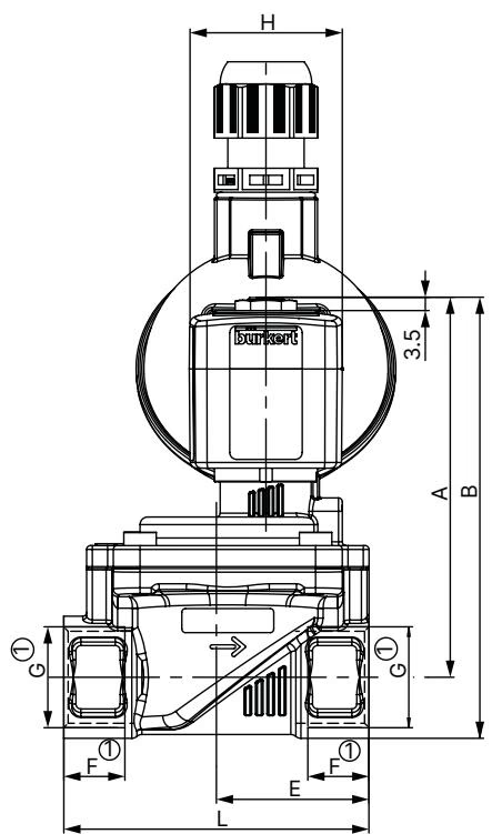
Dimensions for the Type 6281 DN 10 stainless steel ATEX cable version:
Within the Type 6281 ATEX/IECEx cable series with circuit function A, stainless steel 1.4408 body, and FKM seal material, the standard ordering table identifies the following variants:
| Port Connection | Orifice DN [mm] | Kv Value (Water) [m³/h] | Pressure Range [bar] | Weight [kg] | Article No. (024/AC/DC) | Article No. (230/AC/DC) |
|---|---|---|---|---|---|---|
| G 1/4 | 10 | 1.5 | 0.2 to 16 | 0.62 | 349665 | 349666 |
| G 3/8 | 10 | 1.9 | 0.2 to 16 | 0.59 | 349669 / 20083344* | 349670 |
| G 1/2 | 13 | 3.8 | 0.2 to 16 | 0.84 | 349707 | 349708 |
| G 3/4 | 20 | 8.5 | 0.2 to 16 | 1.20 | 349724 | 349727 |
| G 1 | 25 | 12.0 | 0.2 to 16 | 1.60 | 349742 | 349744 |
| G 1 1/4 | 25 | 12.0 | 0.2 to 16 | 1.70 | 349747 | 349750 |
| G 1 1/2 | 40 | 30.0 | 0.2 to 16 | 3.10 | 349765 | 349767 |
| G 2 | 40 | 30.0 | 0.2 to 16 | 3.30 | 349770 | 349771 |
Variant Distinction
Article number 20083344 corresponds to the 24 V AC/DC version with G 3/8 connection, stainless steel body, and FKM seals, supplied cleaned and degreased for gaseous oxygen service in accordance with code NL02 and DIS 1000020797.
Proper mechanical and electrical installation ensures safe operation within hazardous locations.
Electrical Safety in Hazardous Locations
Isolate power and depressurize the piping system before starting installation, maintenance, or repair. Verify protective earth conductor continuity between the solenoid coil and the valve body before energizing.
Explore similar products in our catalog


