PN16

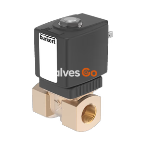
BURKERT 20083624 (Type 6027) is a direct-acting 2/2-way NC plunger solenoid valve with Bürkert 40x40 flange, stainless steel body, EPDM seals, Kick and Drop electronics, and 0-8 bar pressure range.
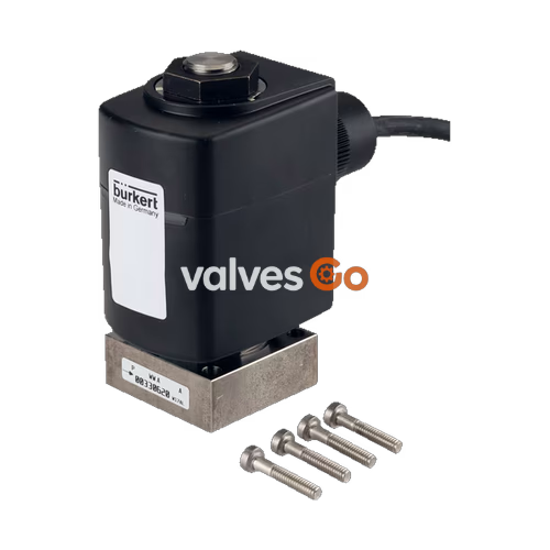
BURKERT 20083624 (Type 6027) is a direct-acting 2/2-way plunger solenoid valve configured with a Bürkert 40 x 40 mm flange connection (variant A1), a 4.5 mm orifice diameter, and stainless steel construction. Operating under circuit function A (normally closed, pressure port 1 P/NC), this complete valve unit controls neutral and slightly aggressive gases and liquids across an operating pressure range of 0.00 bar to 8.00 bar. It includes integrated Kick and Drop dual-coil electronics operating at 24 V AC/DC (50/60 Hz), providing reduced holding power during continuous operation.
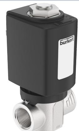
The unit is sealed with ethylene-propylene diene rubber (EPDM) on both the seat seal and external joint interfaces, permitting media temperatures from -30 °C to +120 °C and ambient temperatures from -30 °C to +70 °C. The valve features a welded joint between the stopper and core guide tube to prevent external leakage under pressure. Electrical connection is established via a DIN EN 175301-803 Form A plug pattern, supplying IP65 environmental ingress protection when connected using the enclosed cable plug.
| Specification Parameter | Technical Value |
|---|---|
| Valve Type | 6027 |
| Article Number (SKU) | 20083624 |
| Circuit Function | Circuit function A (2/2-way, normally closed) |
| Fluidic Ports | 2 ports, 2 switching positions |
| Orifice Diameter (DN) | 4.50 mm (11/64") |
| Flow Coefficient ($K_v$) | 0.63 m³/h (water at +20 °C) |
| Pressure Range (Gas & Liquid) | 0.00 bar to 8.00 bar |
| Flow Direction | Above valve seat |
| Body & Seat Material | Stainless steel 1.4404 / 316L |
| Seal Material | EPDM (seat seal and external seal) |
| Port Connection | Bürkert flange 40 x 40 mm (variant A1) |
| Nominal Voltage | 24 V AC/DC (50/60 Hz) |
| Voltage Tolerance | ±10% |
| Integrated Electronics | Kick and Drop dual-coil power reduction technology |
| Thermal Insulation Class | Epoxy coil class H |
| Duty Cycle | 100% continuous operation (ED) |
| Medium Temperature | -30.00 °C to +120.00 °C |
| Ambient Temperature | -30.00 °C to +70.00 °C |
| Ingress Protection | IP65 (with DIN EN 175301-803 Form A cable plug) |
| Cable Plug Inclusion | Enclosed in standard delivery package |
Type 6027 uses a direct-acting plunger design that operates independently of pilot differential pressure, allowing full flow control from 0 bar up to nominal pressure rating. When the solenoid coil is energized, electromagnetic force lifts the internal stainless steel plunger directly from the valve seat against the return spring force, opening the flow path. De-energizing the coil allows the spring to drive the plunger back onto the seat, closing the port.
To ensure structural integrity and zero external leakage, the stopper and plunger guide tube are welded together into a hermetic pressure-containing assembly. The coil assembly is encapsulated in chemically resistant epoxy resin and bolted onto the core guide tube, producing a vibration-proof assembly. The coil can be rotated around the tube axis to position electrical terminals during field installation.
INFO
Because the coil is isolated from the fluid path, the solenoid assembly can be replaced or serviced without venting fluid pressure or opening the fluid process line.
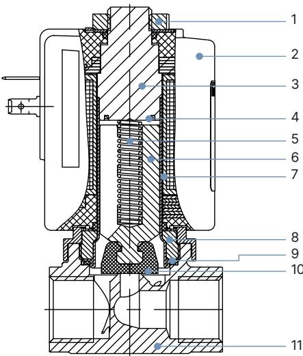
The internal components and housing parts conform to strict material standards for corrosive compatibility and mechanical resilience:
| Item No. | Component Element | Material Specification |
|---|---|---|
| 1 | Nut | DIN 176 thick-film passivated or stainless steel |
| 2 | Coil | Epoxy encapsulation (thermal class H) |
| 3 | Stopper | Stainless steel 1.4113 (AISI 434) |
| 4 | Shading Ring | Silver (for stainless steel body variants) |
| 5 | Spring | Stainless steel 1.4310 (AISI 301) |
| 6 | Plunger | Stainless steel 1.4113 (AISI 434) |
| 7 | Core Guide Tube | Stainless steel 1.4303 (AISI 305/308) |
| 8 | Threaded Nipple | Stainless steel 1.4305 (AISI 303) |
| 9 | External Seal | EPDM (ethylene-propylene diene rubber) |
| 10 | Valve Seat Seal | EPDM (ethylene-propylene diene rubber) |
| 11 | Housing Body | Stainless steel 1.4404 / 316L (CF3M) |
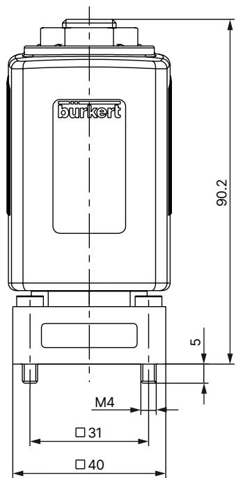
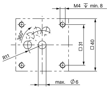
Article 20083624 features a standardized Bürkert 40 x 40 mm concentric flange connection (variant A1). This design allows manifold block mounting and compact skid integration.
Article 20083624 incorporates Kick and Drop dual-coil technology. When energized, the internal electronics deliver a short-term high-power pulse (cold inrush power: 85 W for 500 ms) to pull the plunger open against system pressure. Immediately following pull-in, the circuit drops power to an energy-saving holding level (cold holding power: 8.5 W; warm holding power: 7.0 W).
| Coil Variant | Inrush Power (Cold) | Holding Power (Cold) | Holding Power (Warm) |
|---|---|---|---|
| 42 mm (Size K) Kick and Drop AC/DC | 85 W (500 ms) | 8.5 W | 7.0 W |
| 42 mm (Size K) ATEX AC/DC | 44 W (500 ms) | 6.5 W | 5.5 W |
Operational ambient temperatures for Kick and Drop coils depend on operational switching frequency:
Installation Position
The valve can be installed in any physical position, although mounting with the solenoid actuator vertically upright is recommended to minimize particulate settling inside the core guide tube.
Maintenance Caution
Before disconnecting lines or loosening the solenoid coil nut, completely depressurize the fluid system and disconnect electrical power. Do not turn tightly fastened retaining nuts beyond the specified installation torque (AF 14: 5 Nm; AF 22: 15 Nm).
| Accessory Description | Technical Features | Article Number |
|---|---|---|
| Type 2509 Cable Plug | Form A DIN EN 175301-803, without wiring, 0-250 V AC/DC, ATEX Cat. 3 GD / UL 429 compliant | 137943 |
| Type 2518 Cable Plug | Form A DIN EN 175301-803, without wiring, 0-250 V AC/DC | 314802 |
| Type 2518 Cable Plug | Form A DIN EN 175301-803, with LED and varistor, 12-24 V AC/DC | 314820 |
| Type 2518 Cable Plug | Form A DIN EN 175301-803, with rectifier, LED, and varistor, 12-24 V AC/DC | 314816 |
| Mounting Bracket | Suitable for Type 6020/6027/6240/6440, includes 2x M4x8 screws and lock washers | 282304 |
Explore similar products in our catalog