

PN16

BURKERT 20083802 Type 8640 modular valve island for pneumatics. Features an 11 mm station width, G 1/4 pressure port, IP20 protection, and ATEX/IECEx certification for hazardous areas.
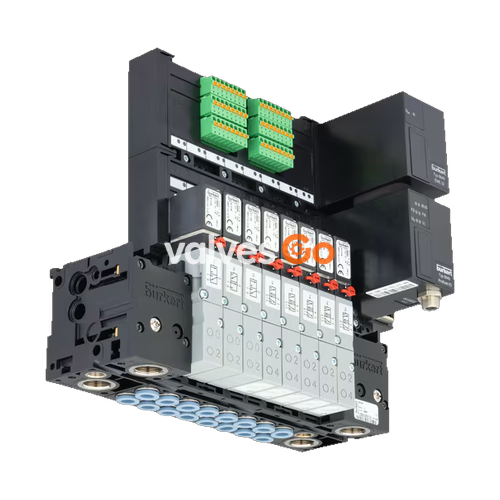
BURKERT 20083802 Type 8640 modular valve island is designed to solve diverse and complex control problems through its systematic modular construction and combination of pneumatic and electrical interfaces. By assembling a row of pneumatic modules with different numbers of valves, 2 to 24 valve functionalities can be realized on a single valve unit. Electrical connectivity is achieved via fieldbus interfaces, common connection (parallel connection technique), or multipin interfaces. The bodies and connection modules are manufactured from high-quality plastic (polyamide) and assemble easily using built-in snap connectors.

The specific model 20083802 (revision 3) is configured with an 11 mm add-on dimension per station, a G 1/4 pressure port, and a D6 working port located at the bottom of the pneumatic module. It operates within a nominal pressure range of 2.5 bar to 7.0 bar and supports a medium temperature of 0 °C to 50 °C. The unit provides IP20 protection and carries ATEX/IECEx certifications (II 2 G Ex ia IIC T4...T6 Gb, Ex ia IIC T6) for use in hazardous environments.
The Type 8640 valve island accommodates various pilot valves depending on the application requirements. The maximum flow rate depends on the specific valve function selected.
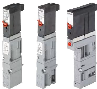
The pilot valves Type 6524 (single and double valve) and Type 6525 (single valve) consist of a pilot flipper solenoid valve Type 6144 and a pneumatic seat valve. The circuit function allows switching of high pressures with low power consumption and short switching times. These pilot valves are equipped with a manual override as standard.
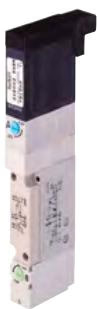
The solenoid valve Type 0460 consists of an aluminum pneumatic valve body fitted with a double coil pilot valve. This principle allows switching of high pressures together with low power consumption and fast switching times. All valves are equipped with manual override as standard.
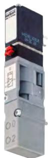
The solenoid valves Type 6526 and Type 6527 consist of a pneumatic valve body fitted with a Type 6106 rocker solenoid valve. The circuit function allows high pressures to be switched with low power consumption and short switching times.
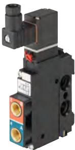
The solenoid valve Type 5470 consists of a pneumatic valve body fitted with a Type 6106 rocker pilot valve. An armature with a tilting bearing tilts within the body of the pilot valve and switches the valve. The minimal tilting movement of the rocker is non-wearing, and basic lubrication is unnecessary.
Electrical connectivity for the Type 8640 system is managed through different module types:
| Module Type | Description |
|---|---|
| Collective connection module | Connection via individual stranded wires, looped-through ground potential, max. 24 valves, IP20 protection, screw-type terminals. |
| Multi-pin module | Max. 24 valves, IP20 protection, electrical connection plug D-Sub (2-pin). |
| Fieldbus modules | Supports PROFIBUS DP, PROFINET IO, EtherNet/IP, Modbus TCP. Max. 24 valves, max. 32 digital inputs (in connection with EME module). |
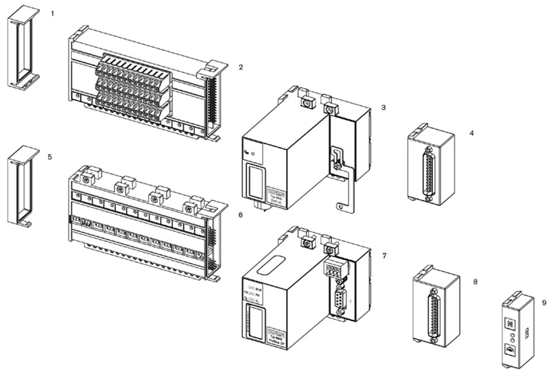
| No. | Element |
|---|---|
| 1 | Electrical end module, left |
| 2 | Terminal module for feedback |
| 3 | Extension module for electrical inputs |
| 4 | Multi-pin digital inputs (initiators) |
| 5 | Electrical end module, left |
| 6 | Basic electrical module standard |
| 7 | Fieldbus module |
| 8 | Multipin valve outputs |
| 9 | Common connection module |
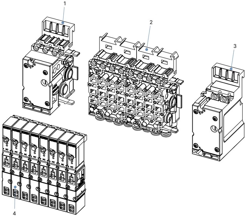
| No. | Element |
|---|---|
| 1 | Pneumatic connection module, left |
| 2 | Basic pneumatic modules |
| 3 | Pneumatic connection module, right |
| 4 | Valves (for example 5/2-way) |
DANGER
Risk of injury due to high pressure and escaping medium. Switch off the pressure before working on the device or system. Vent or drain the pipes.
WARNING
Risk of injury from quickly accelerating device parts and unconnected compressed air hoses flapping around. Before applying pressure to the valve, check all hose connections and fittings for tight, secure fit.
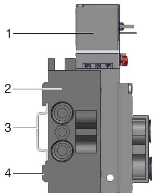
The valve block can be installed on a standard rail (35 x 15 or 35 x 7.5 EN 50022) by hooking the upper groove into the rail and snapping the lower clamping pieces into place. Alternatively, the valve block can be fastened directly to a wall using M4 screws.
Push the hose lines into the push-in connections of the solenoid valves until they come to a stop. Use PTFE tape or an elastomer seal for sealing threaded connections. Ensure that the appropriate combination of hose material (polyamide or polyurethane) and push-in connector is used, as different materials require different holding forces.
Screw on the cable plug observing the maximum tightening torque of 0.3 Nm. Check that the flat seal is correctly fitted. Connect the protective conductor and check electrical continuity between the coil and the housing to prevent the risk of electric shock.
TIP
If continuous operation is interrupted, a minimum activity of 1-2 switching operations per day is recommended for the duration of the downtime to ensure functional reliability.
Explore similar products in our catalog


