

PN16

BURKERT 20085620 Type 8640 is a modular pneumatic valve island featuring mixed valve population, G 1/4 supply ports, D6 push-in working connections, 2.5 to 10 bar operating pressure, and DIN-rail mounting.
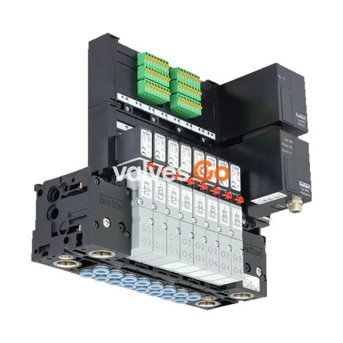
BURKERT 20085620 Type 8640 is a modular pneumatic valve island configured with a mixed valve population and 11 mm station width, designed for controlling neutral media and compressed air in industrial automation systems. Operating under revision 3 engineering standards, this valve block variant utilizes single wiring without internal bus communication and provides an ingress protection rating of IP20. Pneumatic supply is delivered through G 1/4 ports, with working connections routed out the bottom of the pneumatic module via D6 push-in connectors. The assembly supports an operating pressure range between 2.5 bar and 10 bar across a medium temperature span of 0 °C to 50 °C and an ambient temperature span of 0 °C to 55 °C.
| Specification Parameter | Value / Detail |
|---|---|
| Model Article Number | 20085620 |
| Valve Type Family | Type 8640 (utilizing Type 5470 valves with Type 6106 pilot valves) |
| Hardware Generation | Revision 3 |
| Valve Population Type | Mixed valve population (3/2-way and 4/2-way functions) |
| Station Width | 11.00 mm |
| Supply Connection | G 1/4 |
| Working Port Size & Position | D6 push-in connectors, located at bottom of pneumatic module |
| Nominal Pressure Range | 2.50 bar to 10.00 bar |
| Medium Temperature Range | 0 °C to +50 °C |
| Ambient Temperature Range | 0 °C to +55 °C |
| Operating Fluid | Filtered compressed air (particle size max. 10 μm, lubricated or unlubricated), neutral gases (5 μm filtering) |
| Pilot Operating Pressure | 2 to 10 bar (at least 70% of operating pressure) |
| Pressure Difference Requirement | Minimum 2 bar difference between port 1 and port 3 |
| Ingress Protection Rating | IP20 (max. with suitable connection) |
| Control Variant | Single wiring (without internal bus communication, 0 digital inputs) |
| Mounting Standard | DIN-rail installation (EN 50022 35 x 15 or 35 x 7.5) |
Type 8640 valve islands integrate solenoid valves constructed from a 3/2-way Type 6106 pilot valve, a main valve body equipped with diaphragm seals, seat seals, and A/B connection plates. Individual stations assemble onto pneumatic base modules to form a rigid manifold block.

| Item | Designation |
|---|---|
| 1 | Pilot valve Type 6106 |
| 2 | Exhaust port 3 |
| 3 | Pressure port 1 |
| 4 | Working port 4 |
| 5 | Working port 2 |
| 6 | Manual override |
| 7 | Cable plug Type 2506 / Type 2516 |
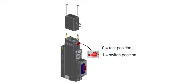
Manual override allows actuation of each valve during setup and testing without requiring electrical signals.
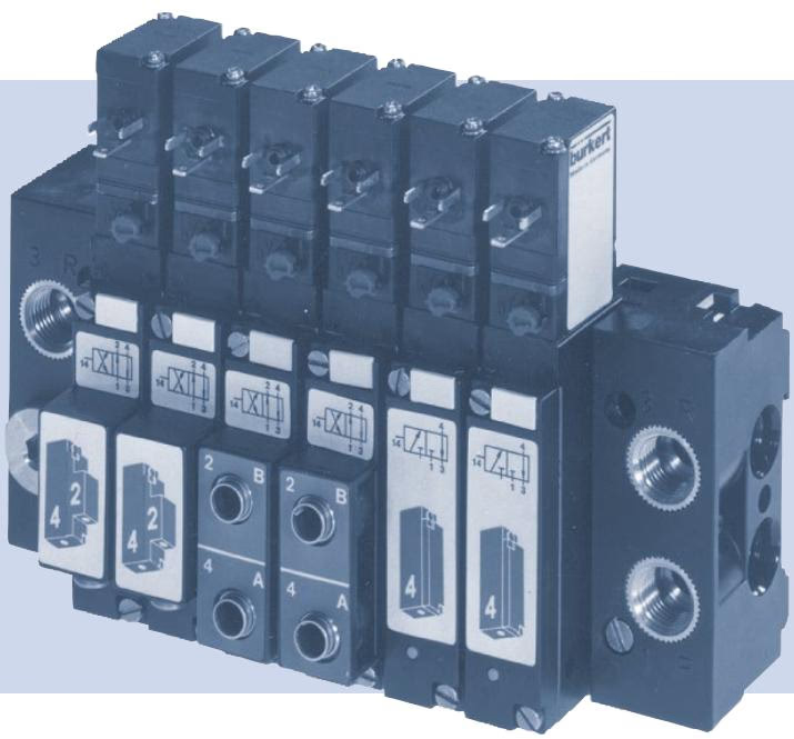
Type 8640 accommodates several switching configurations. Port connections are numbered according to standard pneumatic designations: port 1 indicates the pressure supply, ports 2 and 4 serve as working outlets, and port 3 serves as the exhaust channel.
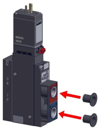
A 4/2-way valve can be converted into a 3/2-way valve by plugging one of the working outlets with a dedicated stopper:
| Port 2 | Port 4 | Resulting Circuit Function |
|---|---|---|
| Closed | Open | Function C (Normally Closed 3/2-way) |
| Open | Closed | Function D (Normally Open 3/2-way) |
Valves mount onto modular pneumatic base rails (such as Type MP05 modules). Standard operating orientation permits any installation position, with vertical mounting (solenoid actuator on top) preferred.
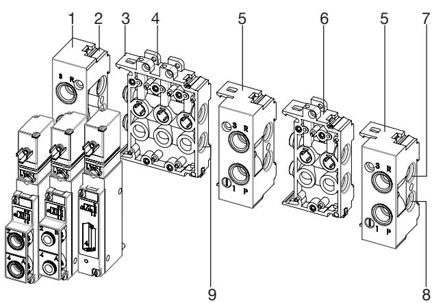
| Item | Designation |
|---|---|
| 1 | Left connection module |
| 2 | Latch tab |
| 3 | Latch hook |
| 4 | Base modules 3-fold |
| 5 | Right connection module |
| 6 | Base modules 2-fold |
| 7 | Exhaust channel 3(R) |
| 8 | Supply channel 1(P) |
| 9 | O-ring |
Pilot Solenoid Rotation
If space constraints require an alternative cable exit, the solenoid operator can be rotated 180°. Remove the M2 screw, lift the coil from the valve body, rotate it 180°, reseat it, and retighten in two stages: first increment to 0.1 ±0.05 Nm, followed by a final tightening to 0.2 ±0.05 Nm.
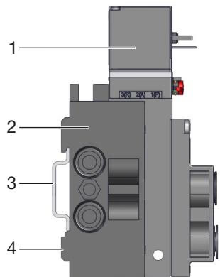
| Item | Component Description |
|---|---|
| 1 | Electrical connection (rotatable by 180°) |
| 2 | Wall mounting bracket |
| 3 | Standard rail 35 x 15 or 35 x 7.5 EN 50022 |
| 4 | Connection module |
When threading fittings into port blocks, adhere strictly to the following torque limits:
| Port Size | Port Identification | Recommended Torque [Nm] | Maximum Torque [Nm] |
|---|---|---|---|
| G 1/4 / NPT 1/4 | P (Supply), R/S (Exhaust) | 4 to 7 | 20 |
| G 1/8 / NPT 1/8 | P, R/S, and A/B outlets | 3 to 6 | 7 |
Tubing lines must meet strict dimensional and material criteria to prevent pull-out and leakage under pressure:
| Tubing Material | Outer Diameter (OD) [mm] | Permitted OD Deviation [mm] |
|---|---|---|
| Polyamide (PA) | 3 to 10 | ±0.08 |
| Polyamide (PA) | 12 to 16 | ±0.10 |
| Polyurethane (PU) | 3 to 8 | ±0.10 |
| Polyurethane (PU) | 10 to 16 | ±0.15 |
Every inserted tube must satisfy the tensile test holding capacity defined by DIN ISO 14743:2020:
| Metric Tube OD [mm] | Imperial Equiv. [in (mm)] | PA Minimum Tensile Force [N] | PU Minimum Tensile Force [N] |
|---|---|---|---|
| 3 | 1/8 (3.17) | 60 | 25 |
| 4 | 5/32 (4.00) | 70 | 50 |
| 6 | 1/4 (6.35) | 120 | 100 |
| 8 | 5/16 (8.00) | 170 | 150 |
| 10 | 3/8 (9.52) | 250 | 200 |
| 12 | 1/2 (12.70) | 300 | 200 |
| 14 | — | 300 | 250 |
| 16 | 5/8 (16.00) | 350 | 300 |
Soft Tubing Retention
When utilizing flexible polyurethane (PU) tubing, install support sleeves (ID 20099400) inside the hose end to maximize retention stability and prevent sealing deformation within the push-in gripping claws.
BURKERT 20085620 features single-wired connections. For cable connection, use approved cable plugs conforming to DIN EN 175301-803 Form C (such as Type 2516).
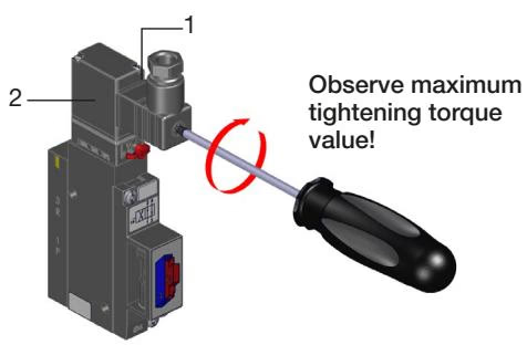
| Item | Description |
|---|---|
| 1 | Flat gasket seal |
| 2 | Cable plug (Type 2516 or compliant DIN EN 175301-803 Form C) |
| Parameter | Protective Conductor Test Specification |
|---|---|
| Maximum Resistance | 0.1 Ω |
| Test Voltage | 12 V |
| Test Current | 1 A |
When equipped with impulse coils, strict electrical polarity must be maintained according to the coil label. Control signals require a minimum pulse duration of 50 ms.
| Plug Terminal Polarity | Pilot Valve State | Pneumatic Channel Effect |
|---|---|---|
| (+) on pin 2 / (-) on pin 1 | Pilot valve opened | 1 connects to 4 (Function C) / 1-3, 2-3 (Function G) |
| (+) on pin 1 / (-) on pin 2 | Pilot valve closed | 4 vents to 3 (Function C) / 1-2, 4-3 (Function G) |
Depressurize Before Servicing
Prior to performing maintenance, isolate pneumatic supply lines, vent all trapped pressure from the manifold, and disconnect electrical power. Secure the system against accidental restart.
| Operational Fault | Probable Cause | Corrective Action |
|---|---|---|
| Valves fail to switch | Missing or insufficient electrical supply voltage | Verify supply wiring; ensure voltage conforms to coil type label. |
| Valves fail to switch | Manual override engaged in locked position | Reset manual override mechanism back to zero position. |
| Valves fail to switch | Insufficient pressure supply | Establish larger-capacity air supply; verify minimum operating pressure is ≥ 2 bar. |
| Delayed switching or continuous venting at exhaust ports | Supply air pressure too low | Ensure operating supply is ≥ 2 bar; check upstream regulators and filters. |
| Delayed switching or continuous venting at exhaust ports | System pressurized while valves were in energized state | Ensure valves are in de-energized rest position before applying air pressure. |
| Delayed switching or continuous venting at exhaust ports | Silencers undersized, clogged, or generating backpressure | Clean dirty exhaust silencers or install larger silencer/expansion chambers. |
| Delayed switching or continuous venting at exhaust ports | Particulate contamination inside pilot or main valve seat | Apply pulsed air bursts through exhaust lines to clear debris, or replace valve capsule. |
| External leakage across valve block | Missing, damaged, or pinched O-rings between modules | Disassemble sub-blocks and replace missing or pinched inter-module O-rings. |
| External leakage across valve block | Missing or misaligned flat gasket seal between valve body and base plate | Inspect base seal interface; install new flat gasket seated in proper orientation. |
Explore similar products in our catalog


