
Skip to content
Modular ConfigurationAirLINE QuickIP20DIN-rail Installation

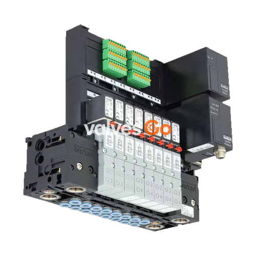
BURKERT 20089139 Type 8640 Modular Valve Island for Pneumatics

Burkert Type 8640 modular valve island (SKU 20089139). Features a compact design, AirLINE Quick compatibility, and flexible pneumatic/electrical interfaces. IP20, 2-8 bar.
BURKERT 20089139 Type 8640 Modular Valve Island for Pneumatics

The BURKERT Type 8640 valve unit system is designed to solve diverse and complex control problems due to its systematic modular construction and combination of pneumatic and electrical interfaces. By putting together a row of pneumatic modules with different numbers of valves, 2 to 24 valve functionalities may be realized on one valve unit. Electrical connectivity is achieved by either fieldbus interfaces, common connection (parallel connection technique) or multipin interfaces. The valves allow different applications to be covered. Bodies and connection modules are made of high-quality plastic (polyamide) and are easy to assemble by means of the built-in snap connectors.

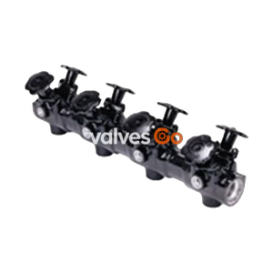
BURKERT 20089139 BURKERT Type 8640 modular valve island overview

Key Features

  • Compact design
  • Modular configuration
  • Higher flexibility in control cabinet due to AirLINE Quick
  • Simple exchange of valves (with option “P-shut-off” – also possible during operation)

General Technical Data

FeatureSpecification
Body MaterialPA (polyamide), aluminium (depending on valve type)
Seal MaterialFKM, NBR and PUR
Number of valve slotsMax. 24 (Max. 12 for impulse and double valves with multipol/fieldbus)
Maximum number of valve functionsMax. 48 (only for individual wiring and multiple connection)
Operating voltage24 V DC (±10% tolerance)
Operating mediumOil-free or lubricated compressed dry air, neutral gases (5 μm filter recommended)
Compressed air qualityISO 8573-1: 2010, Class 7.4.4
Degree of protectionIP20 (IP65 in closed control cabinets)
Installation positionAs required, preferably with actuator upright

Product Connections

Collective Connection Modules and Multipole Modules

  • Collective connection module: Connection via individual stranded wires, looped-through ground potential, max. 24 valves, degree of protection IP20, screw-type terminals.
  • Multi-pin module Valve outputs: Max. 24 valves, degree of protection IP20, electrical connection plug D-Sub (2-pin).

Fieldbus Modules

  • PROFIBUS DP: Max. 24 valves, max. 32 digital inputs, transmission rates up to 12 MBaud, bus connection D-Sub (9-pin).
  • PROFINET IO, EtherNet/IP, Modbus TCP: Max. 24 valves, max. 32 digital inputs, transmission rates 10/100 MBits/s with Auto Crossover, bus connection RJ45 (2x).

Product Design and Assembly

Electronics

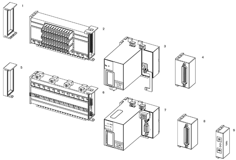
BURKERT 20089139 BURKERT Type 8640 electronics assembly diagram

  1. Electrical end module, left
  2. Terminal module for feedback
  3. Extension module for electrical inputs
  4. Multi-pin digital inputs (initiators)
  5. Electrical end module, left
  6. Basic electrical module standard
  7. Fieldbus module
  8. Multipin valve outputs
  9. Common connection module

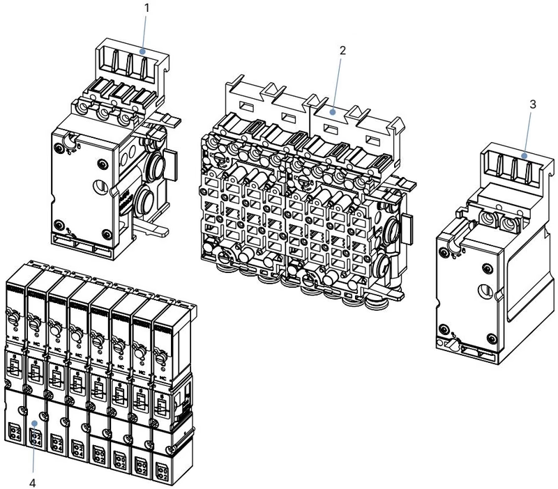
Pneumatics 11 mm width per station

BURKERT 20089139 BURKERT Type 8640 pneumatics 11 mm width per station assembly

  1. Pneumatic connection module, left
  2. Basic pneumatic modules
  3. Pneumatic connection module, right
  4. Valves (for example 5/2-way)

Installation

WARNING

Risk of injury due to high pressure and escaping medium. Switch off the pressure before working on the device or system. Vent or drain the pipes. Risk of injury due to electric shock. Switch off voltage before working on the device or system. Secure against reactivation.
Valve Block Installation

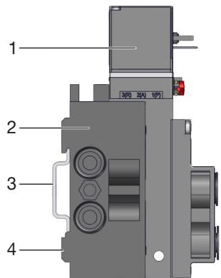
BURKERT 20089139 BURKERT Type 8640 valve block installation on standard rail

Standard rail installation:

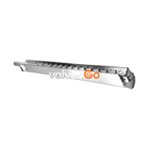
  1. Hook the valve block with the upper groove into the standard rail (35 x 15 or 35 x 7.5 EN 50022).
  2. Snap the lower clamping pieces into the standard rail.
  3. Tighten the screws on the clamping pieces.

Wall installation: Fasten the valve block directly to the wall with M4 screws.

Pneumatic Installation

TIP

Recommended action for push-in connectors: Ensure that the appropriate combination of hose material (polyamide or polyurethane) and push-in connector is used. Cut the hose straight. Press the hose into the push-in connector with sufficient force so that it is held correctly by the claws.
  • Check the hose lines for contamination and clean them.
  • If necessary, install dirt traps upstream of the valve inlet (≤ 5 µm).
  • Push the hose lines into the push-in connections of the solenoid valves until they come to a stop.
  • Connect the supply and working lines to the valve block.

Electrical Installation of Cable Plugs

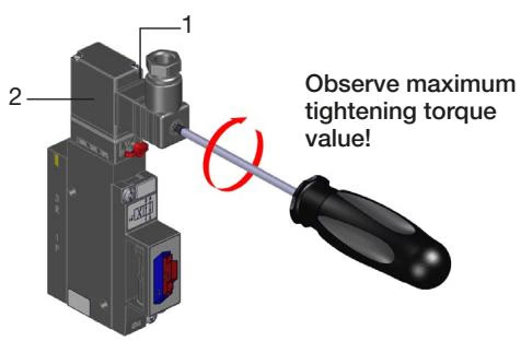
BURKERT 20089139 BURKERT Type 8640 electrical installation of cable plugs

  1. Screw on the cable plug (observing the maximum tightening torque of 0.3 Nm).
  2. Check that the seal is correctly fitted.
  3. Connect the protective conductor and check electrical continuity between coil and housing.