PN25

BURKERT 20090698 (Type 2961) is a manually operated DN50 2-way globe control valve with welded ends, stainless steel body, PTFE seat seal, PN25 rating, and an equal percentage flow characteristic with 37 m³/h Kvs.
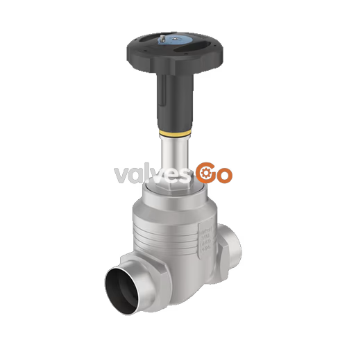
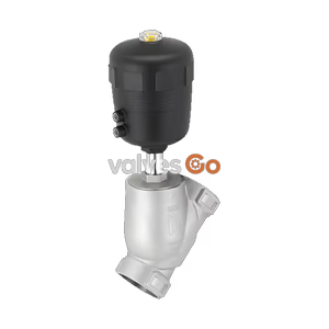
BURKERT 20090698 (Type 2961) is a manually operated 2-way globe control valve engineered for continuous flow regulation of neutral gases, water, steam, alcohols, oils, fuels, hydraulic fluids, saline solutions, lyes, and organic solvents. Built for process installations requiring reproducible manual flow setting, this article features a nominal connection size of DN 50 (NPS 2) with welded pipe ends conforming to DIN 11850 Series 2 / DIN 11866 Series A / DIN EN 10357 Series A (outer tube diameter 53.0 mm, wall thickness 1.5 mm). The valve configuration combines a 316L/CF3M stainless steel globe body, an exchangeable 50 mm orifice seat, a PTFE soft seat seal providing DIN EN 60534-4 Leakage Class VI shut-off, and a high-performance PPS manual actuator with an optical stroke scale.

Equipped with an equal percentage parabolic control cone providing a theoretical rangeability of 50:1, the valve reaches a nominal flow coefficient Kvs of 37 m³/h (Cv 43.1 gpm) across a 26 mm stroke. Flow passes below the seat (flow-to-open), preventing water hammer during closure. The self-adjusting PTFE V-ring gland packing includes integrated spring compensation, maintaining stem sealing without manual adjustment.
BURKERT Type 2961 operates by manually rotating the polyphenylene sulphide (PPS) handwheel. Counterclockwise rotation drives the stem upward, lifting the parabolic control cone away from the replaceable valve seat to establish medium flow. Clockwise rotation forces the cone downward against the flow until the PTFE seat seal contacts the stainless steel seat ring, achieving bubble-tight shut-off. A precision spindle guide in 1.4404 (316L) stainless steel with PTFE filling supports the spindle to maintain accurate flow characteristics under demanding line vibrations.
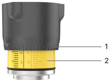
The manual actuator incorporates a multi-turn optical position indicator. Handwheel size M (Ø 110 mm) provides an axial spindle slope of 1.75 mm per complete 360° turn. The handwheel rim carries a 50-division radial scale, while the actuator neck reveals a reproducible stroke scale as the handwheel lifts. This dual-scale arrangement permits repeatable positioning across 50 increments per revolution.
Visual Indicator Setting Notice
The visibility of the stroke scale does not directly correlate with the fully closed position across all body types. Depending on the valve design, the repeatable stroke scale may not be visible when open, or may remain partly visible when closed. Always reference the flow curve table and calibrate the zero position against the seat touch point.
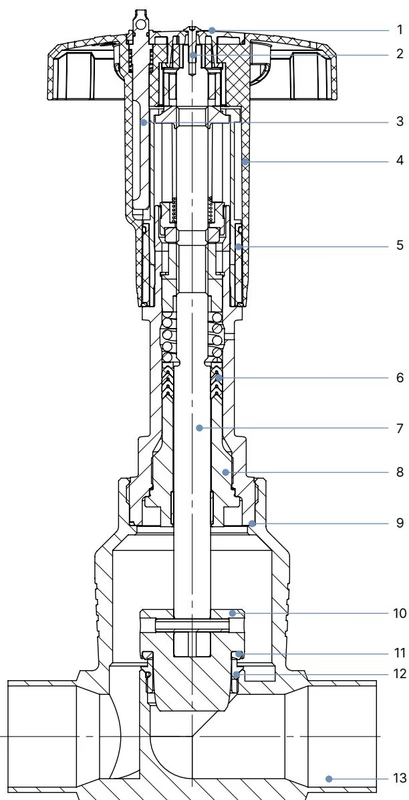
| Item | Component | Material |
|---|---|---|
| 1 | Cover | Polyamide (PA) |
| 2 | Screw | Stainless steel 1.4301 |
| 3 | Locking device | Stainless steel 1.4305 |
| 4 | Handwheel | Polyphenylene sulphide (PPS) |
| 5 | Visual position indicator with scale | Polyamide (PA) |
| 6 | Packing gland | PTFE V-rings (filled), with spring compensation |
| 7 | Stem | Stainless steel 1.4401 or 1.4404 |
| 8 | Spindle guide | Stainless steel 1.4404 (316L), PTFE filled |
| 9 | Housing seal | Graphite |
| 10 | Control cone | Stainless steel 1.4571 |
| 11 | Seat seal | PTFE (Polytetrafluoroethylene) |
| 12 | Valve seat with O-ring | Stainless steel 1.4571, EPDM |
| 13 | Valve body | Stainless steel 316L / CF3M |
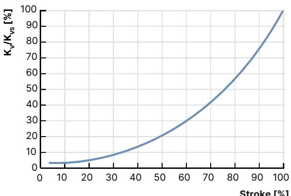
Flow characteristics conform to DIN EN 60534-2-4. For seat sizes greater than DN 10, the turn-down ratio KvR threshold is defined at 5% of valve stroke. The theoretical rangeability (Kvs / Kv0) is 50:1. The table below lists the intermediate Kv values measured with water at incremental stroke percentages for article 20090698 (DN 50, seat size 50 mm), along with smaller exchangeable seat trims available for the DN 50 globe valve body.
| Port Size DN | Seat Size [mm] | Handwheel Size | Max. Pressure [bar(g)] | Leakage Class | 5% | 10% | 20% | 30% | 40% | 50% | 60% | 70% | 80% | 90% | 100% (Kvs) |
|---|---|---|---|---|---|---|---|---|---|---|---|---|---|---|---|
| 50 | 50 (20090698) | 110 (M) | 25 (20)¹ | VI (PTFE) | 0.90 | 1.1 | 1.9 | 2.9 | 4.5 | 6.8 | 10.5 | 15.5 | 22.0 | 29.5 | 37.0 m³/h |
| 50 | 40 | 110 (M) | 25 (20)¹ | VI (PTFE) | 0.60 | 0.70 | 1.0 | 1.7 | 2.6 | 4.0 | 5.9 | 9.2 | 14.0 | 18.9 | 24.5 m³/h |
| 50 | 32 | 110 (M) | 25 (20)¹ | VI (PTFE) | 0.48 | 0.60 | 0.90 | 1.3 | 2.1 | 3.2 | 4.6 | 6.9 | 11.6 | 16.0 | 21.0 m³/h |
| 50 | 20 | 110 (M) | 25 (20)¹ | II (Steel) | — | 0.14 | 0.25 | 0.38 | 0.57 | 0.85 | 1.3 | 1.9 | 2.8 | 4.1 | 6.3 m³/h |
¹ Pressure derating in parentheses (20 bar) applies to compressible fluids of Group 1 (hazardous gases and vapors according to Pressure Equipment Directive 2014/68/EU).
The maximum permissible working pressure of BURKERT process valves is governed jointly by the body pressure rating (PN 25 / Class 150), connection standards, and medium temperature.
| Temperature [°C] | Maximum Permissible Operating Pressure [bar(g)] |
|---|---|
| -10 to +50 °C | 25.0 bar |
| +100 °C | 24.5 bar |
| +130 °C (PTFE limit) | 23.0 bar |
| +150 °C | 22.4 bar |
| +200 °C | 20.3 bar |
| +230 °C | 19.0 bar |
| Sealing Material | Leakage Class (DIN EN 60534-4) | Medium Temperature Range | Application Notes |
|---|---|---|---|
| PTFE (Article 20090698) | Class VI (Soft seal) | -40 °C to +130 °C | Bubble-tight shut-off; eliminates need for secondary isolation valve below 130 °C. |
| PEEK (Optional) | Class VI (Soft seal) | -10 °C to +230 °C | Recommended for medium temperatures > 130 °C. |
| Stainless Steel (Optional) | Class II (Metal-to-metal) | -40 °C to +230 °C | Permissible seat leakage 0.5% of nominal flow; resistant to erosion. |
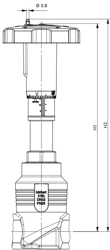
| Nominal Size DN | Nominal Size NPS | Handwheel Size | Handwheel Ø [mm] | Height H1 [mm] | Height H2 (with Lock) [mm] |
|---|---|---|---|---|---|
| 15 | 1/2 | S | 45 | 217 | 224 |
| 20 | 3/4 | S | 45 | 224 | 230 |
| 25 | 1 | S | 45 | 228 | 234 |
| 32 | 1 1/4 | M | 110 | 296 | 303 |
| 40 | 1 1/2 | M | 110 | 301 | 307 |
| 50 (20090698) | 2 | M | 110 | 307 | 313 |
| 65 | 2 1/2 | L | 160 | 361 | 368 |
| 80 | 3 | L | 160 | 369 | 375 |
| 100 | 4 | L | 160 | 379 | 385 |
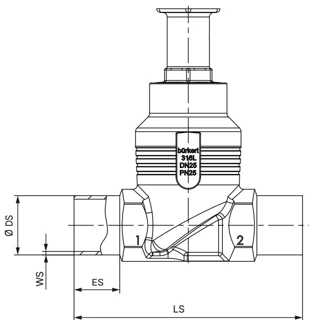
| Nominal Size DN | Body Length LS [mm] | End Depth ES [mm] | Outer Tube Ø DS [mm] | Wall Thickness WS [mm] |
|---|---|---|---|---|
| 10 | 90 | 20 | 13.0 | 1.5 |
| 15 | 90 | 20 | 19.0 | 1.5 |
| 20 | 100 | 20 | 23.0 | 1.5 |
| 25 | 130 | 26 | 29.0 | 1.5 |
| 32 | 140 | 26 | 35.0 | 1.5 |
| 40 | 150 | 26 | 41.0 | 1.5 |
| 50 (20090698) | 175 | 26 | 53.0 | 1.5 |
| 65 | 210 | 26 | 70.0 | 2.0 |
| 80 | 230 | 26 | 85.0 | 2.0 |
| 100 | 260 | 26 | 104.0 | 2.0 |
Before welding the valve body into the pipeline, the manual actuator must be disassembled from the body to protect the internal seals and PTFE packing from thermal degradation.
| Valve Body Nominal Diameter DN | Tightening Torque [Nm] | Tolerance [Nm] |
|---|---|---|
| 10 / 15 | 45 | ±3 |
| 20 | 50 | ±3 |
| 25 | 60 | ±3 |
| 32 | 65 | ±3 |
| 40 | 65 | ±3 |
| 50 (20090698) | 70 | ±3 |
| 65 | 100 | ±3 |
| 80 | 120 | ±5 |
| 100 | 150 | ±5 |
Body Connection Torque Check
In piping installations subjected to severe mechanical vibration or operating temperatures exceeding 140 °C, the threaded body connection can loosen over time. Check the body connection screw torque before initial startup and at regular maintenance intervals.
While article 20090698 is supplied standard without mechanical stroke limitation, the Type 2961 actuator platform supports optional stroke limit adjustment sleeves and handwheel interlocks.
Under normal service conditions following manufacturer guidelines, the Type 2961 manual actuator is maintenance-free. Perform an annual visual inspection of the valve body, pipe connections, and relief bore.
| Problem | Probable Cause | Corrective Action |
|---|---|---|
| Valve seat fails to seal tightly | Particulate debris trapped between plug and seat | Flush line; install upstream strainer |
| Seat seal worn or damaged | Replace closure member / seat seal | |
| Pipeline flow direction reversed | Verify arrow on body; flow must enter below seat | |
| Operating pressure exceeds limit | Check line pressure against type label specifications | |
| Medium leakage at actuator relief bore | Stem packing gland worn | Replace PTFE V-ring gland packing set |
BURKERT Type 2961 conforms to ATEX / IECEx certification EPS 18 ATEX 2 008 X and IECEx EPS 18.0007X (Category 2 mechanical equipment, suitable for Zone 1/21 and Zone 2/22).
| Temperature Class | Maximum Surface Temperature | Permissible Ambient Temperature | Maximum Medium Temperature |
|---|---|---|---|
| T4 | +135 °C | -40 °C to +100 °C | +125 °C |
| T3 | +200 °C | -40 °C to +130 °C | +185 °C |
| T2 | +300 °C | -40 °C to +130 °C | +285 °C |
Electrostatic Discharge Hazard in Hazardous Areas
Sudden electrostatic discharge from insulated conductive components in explosive atmospheres poses an ignition hazard. Connect the valve body to the pipe grounding system. If conductive non-grounded accessories are installed, provide separate potential equalization straps. Clean outer plastic actuator surfaces only using a damp or antistatic cloth.
Explore similar products in our catalog