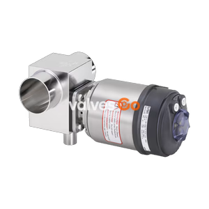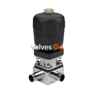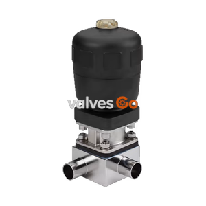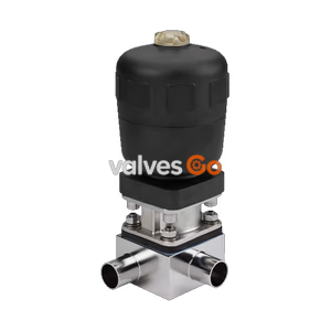
Type 2032

BURKERT 20094791 (Type 2933) is a 2/2-way manual diaphragm valve with DN 25 DIN 32676 Series A clamp, 316L tube body, GYLON/EPDM diaphragm, 0-10 bar rating, -5 °C to 130 °C media, and Kv 13.7 m³/h.
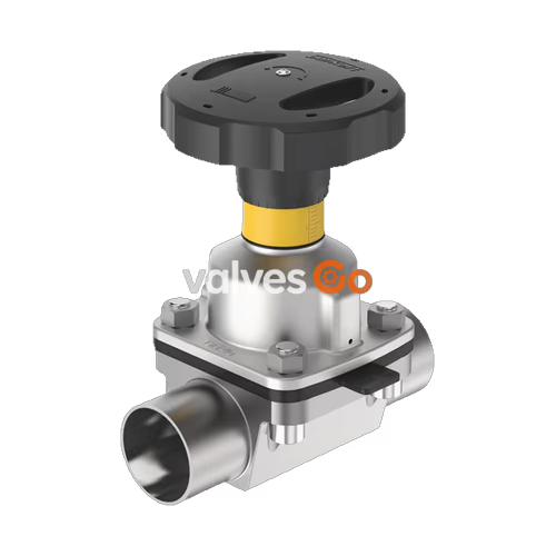
BURKERT 20094791 (Type 2933) is a manually operated 2/2-way diaphragm valve designed for shut-off control in ultra-pure, hygienic, and sterile process lines. Built with a flow-optimised tube valve body (VP) made of stainless steel pipe 1.4435 BN2 / 316L, the unit features zero deadleg geometry to ensure high flow rates and complete media recovery. The fluid port connection is configured as a DN 25 clamp according to DIN 32676 Series A (matching DIN 11850 Series 2 pipe dimensions of 29.0 x 1.5 mm with a 50.5 mm clamp collar).
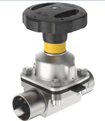
This valve configuration incorporates a diaphragm size 20 sealing element made of GYLON® laminated with an EPDM backing (material code ER), attached via a positive bayonet catch. The manual actuator features an autoclavable polyphenylene sulphide (PPS) handwheel, a stainless steel bonnet (1.4308), an integrated visual position indicator with a 30-position rotation scale, and an adjustable closing limiter to prevent diaphragm damage from overtorquing. The bonnet includes two M5 x 0.5 threaded holes to accept inductive limit switches for electrical position feedback.
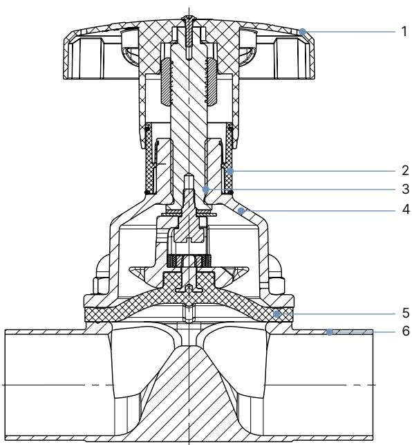
The Type 2933 manual diaphragm valve assembly consists of six functional mechanical elements engineered for aggressive and sanitary working environments:
| Item | Element | Material Configuration for Article 20094791 |
|---|---|---|
| 1 | Handwheel | Polyphenylene sulphide (PPS), size S (∅ 45 mm) |
| 2 | Visual position indicator | Polyamide (PA), stainless steel 1.4305 |
| 3 | Valve spindle | Stainless steel 1.4305 |
| 4 | Diaphragm bonnet | Stainless steel 1.4308 (with 2x M5x0.5 feedback ports) |
| 5 | Diaphragm | GYLON® laminated with EPDM backing (ER), size 20 |
| 6 | Valve body | Stainless steel pipe 1.4435-BN2 / 316L (VP tube body) |
Hygienic Material Conformity
The GYLON® and EPDM laminated diaphragm meets US FDA Code of Federal Regulations, passes USP Class VI biological reactivity testing, and complies with European Regulation (EC) 1935/2004 for food contact materials. Deliveries include an EN 10204 3.1 manufacturer test certificate and a 2.1 diaphragm certificate.
| Technical Parameter | Specification Value |
|---|---|
| Operating medium | Neutral gases, liquids, sterile, highly purified, aggressive or abrasive media |
| Nominal pressure rating | PN 10 (DIN EN 1333) / Class 150 (DIN EN 1759) |
| Permitted medium pressure | 0.00 bar to 10.00 bar |
| Medium temperature (GYLON® / EPDM) | -5 °C to +130 °C (steam sterilisation up to +140 °C for max. 60 min) |
| Ambient temperature (actuator) | -10 °C to +130 °C (short-term exposure up to +150 °C), autoclavable |
| Flow coefficient Kv (water, 20 °C) | 13.7 m³/h (Cv = 16 gal/min) |
| Handwheel diameter (Size S) | 45 mm (slope per spindle rotation: 1.75 mm) |
| Closing torque for handwheel (static) | 3.0 Nm (diaphragm size 20, PTFE / GYLON® at 10 bar static, +10% tolerance) |
| Dynamic tightening torque | 4.5 Nm (+10% tolerance) |
| Fastening screw torque (bonnet to body) | 4.5 Nm (VP tube body, diaphragm size 20, +10% tolerance) |
| Cleaning capability | CIP (Cleaning in Place) and SIP (Sterilisation in Place) compatible |
| Product identification | Data matrix code on body / type label |
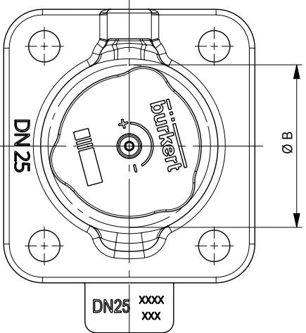
Dimensions for manual actuators across diaphragm sizes 6 through 25 are specified in millimeters:
| Diaphragm Size | Handwheel Size | H1 (Open) [mm] | H2 (Closed) [mm] | ∅ B (Handwheel) [mm] |
|---|---|---|---|---|
| 6 | T | 49 | 42 | 35 |
| 8 | T | 54 | 49 | 35 |
| 15 | S | 84 | 78 | 45 |
| 20 (Article 20094791) | S | 95 | 86 | 45 |
| 25 | S | 101 | 90 | 45 |
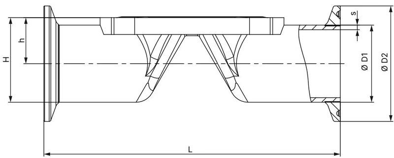
Dimensions for stainless steel tube valve bodies (VP) with clamp connection according to DIN 32676 Series A (DIN pipe) are listed below in millimeters:
| Diaphragm Size | Port Connection DN | ∅ D1 [mm] | s [mm] | ∅ D2 [mm] | L [mm] | h [mm] | H [mm] | Product Key |
|---|---|---|---|---|---|---|---|---|
| 8 | 10 | 13.0 | 1.5 | 34.0 | 89 | 9.85 | 26.85 | TD41 |
| 15 | 15 | 19.0 | 1.5 | 34.0 | 110 | 13.20 | 30.20 | TD42 |
| 15 | 20 | 23.0 | 1.5 | 34.0 | 119 | 15.20 | 32.20 | TD43 |
| 20 (Article 20094791) | 25 | 29.0 | 1.5 | 50.5 | 129 | 18.20 | 43.45 | TD44 |
| 25 | 32 | 35.0 | 1.5 | 50.5 | 148 | 21.20 | 46.45 | TD45 |
| 32 | 40 | 41.0 | 1.5 | 50.5 | 161 | 24.40 | 49.65 | TD46 |
| 40 | 50 | 53.0 | 1.5 | 64.0 | 192 | 31.70 | 63.70 | TD47 |
Turning the handwheel counterclockwise lifts the compressor spindle to open the valve passage; turning clockwise depresses the compressor and presses the diaphragm onto the body weir to close flow.
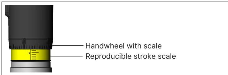
On diaphragm sizes 15 to 50, rotating the handwheel counterclockwise reveals a yellow visual position indicator sleeve and an etched stroke scale located below the handwheel. The collar markings permit 30 discrete rotary positions to set reproducible throttling points.
Manual Closing Force
Turn the handwheel only until the valve seat seals tightly. Applying excessive torque beyond the specified static closing torque of 3.0 Nm damages the diaphragm face and reduces service life.
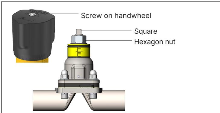
The Type 2933 actuator includes an adjustable minimum stroke limit that functions as a mechanical closing limiter:
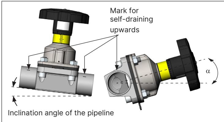
To ensure complete gravity draining in clean utility and biopharmaceutical applications, observe the following mounting guidelines:
Leakage Detection and Relief Bore Orientation
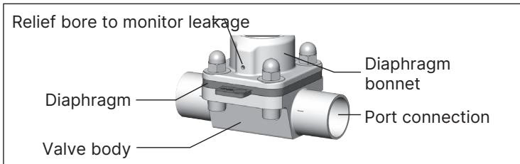 The diaphragm bonnet incorporates relief bores designed to vent fluid and reveal leakage if the diaphragm ruptures. When mounting the valve assembly, ensure at least one relief bore points directly toward the lowest gravitational position to prevent trapped media.
When bolting the actuator to the tube valve body, follow a three-stage crosswise sequence:
Under clean operational conditions, the manual actuator is maintenance-free. Inspect the bonnet relief bore regularly for signs of leakage.
| Accessory / Spare Part Description | Article Number |
|---|---|
| Size 20 replacement diaphragm: GYLON® / EPDM (ER) bayonet, material code PTFE L08 | 693 177 |
| Inductive proximity switch (initiator) M5 x 0.5 | 550412 |
| Inductive proximity switch M5 x 0.5 ATEX certified | 904779 |
| 4-fold nylon locking mechanism with 3 mm bracket | 93719475 |
Explore similar products in our catalog