Up to 99.8% Efficiency

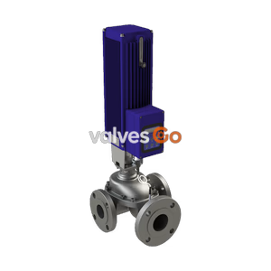
BURKERT 20097830 (Type 3281) electromotive 2-way globe proportional valve features RC 1/2 connection, seat size 10 mm, Kvs 2.25 m3/h, pressure 0-7 bar, büS digital fieldbus, and integrated process controller.
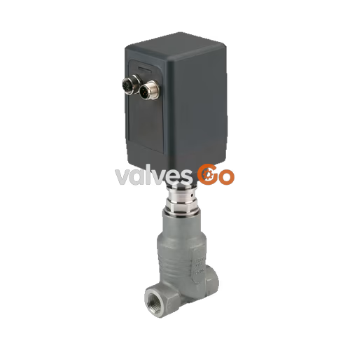
BURKERT 20097830 (Type 3281) is a direct-acting electromotive 2-way globe proportional control valve designed for dosing liquids and gases in continuous control loops. Actuation is performed by an integrated linear stepper motor coupled to a threaded drive spindle, eliminating the need for compressed air infrastructure. The motor draws energy only during stroke adjustments and consumes less than 1 W in holding mode, significantly reducing baseline electrical demand. The fluid path remains completely isolated from the actuator mechanism, ensuring clean operation and reliable service life.
Article 20097830 is configured as a process controller variant with an integrated cascaded PID control structure. It combines an RC 1/2" female threaded connection, a 10 mm nominal seat orifice, a flow coefficient Kvs of 2.25 m³/h, and a controlled operating pressure range of 0 to 7 bar(g). Process communication and parameterization operate via the digital Bürkert system bus (büS, based on CANopen), accompanied by a dedicated M12 socket that accepts an external process transmitter signal.
| Specification Parameter | Technical Value |
|---|---|
| Article Number | 20097830 |
| Valve Type Family | Type 3281 (Electromotive 2-way globe valve) |
| Circuit Function | Direct-acting 2-way proportional valve, closed-loop control |
| Port Connection | RC 1/2" internal thread (ISO 7-1 / EN ISO 228-1) |
| Nominal Seat Diameter | 10 mm (3/8") |
| Flow Coefficient Kvs | 2.25 m³/h (water at +20 °C, 1 bar Δp) |
| Operating Pressure Range | 0 to 7 bar(g) |
| Flow Direction | Against closing direction (below seat, 2 → 1) |
| Operating Voltage | 24 V DC ±10% (max. residual ripple 10%) |
| Operating Power Consumption | < 1 W holding, max. 12 W operating (short-term 20 W) |
| Medium Temperature Range | -20 °C to +130 °C |
| Ambient Temperature Range | -10 °C to +60 °C (observe derating) |
| Fluid Viscosity Limit | Max. 600 mm²/s (cSt) |
| Seat Leakage Rate | Class VI according to DIN EN 60534-4 |
| Nominal Pressure Class | PN 25 (DIN EN 1333) |
| Full Stroke Actuation Time | Approx. 2.5 s (configurable down to 2.2 s or up to 3.2 s) |
| Positioner Dead Band | ±0.5% (corresponding to 1:100 control ratio) |
| Enclosure Protection Rating | IP54 (with matched mating connectors) |
| Unit Weight | Approx. 1.1 kg |
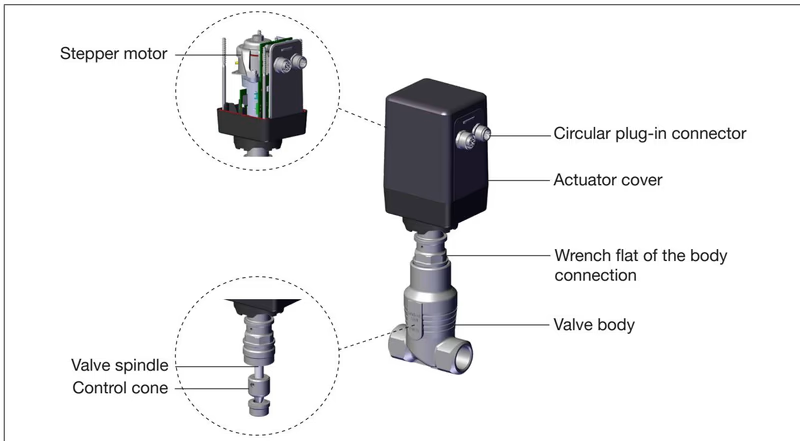
The internal valve spindle is rigidly linked to a precision threaded spindle driven by an electric stepper motor. Rotary motor movements convert into linear stroke action to position the control cone relative to the valve seat. When holding a set position, internal gear holding torque locks the valve spindle in place without motor excitation.
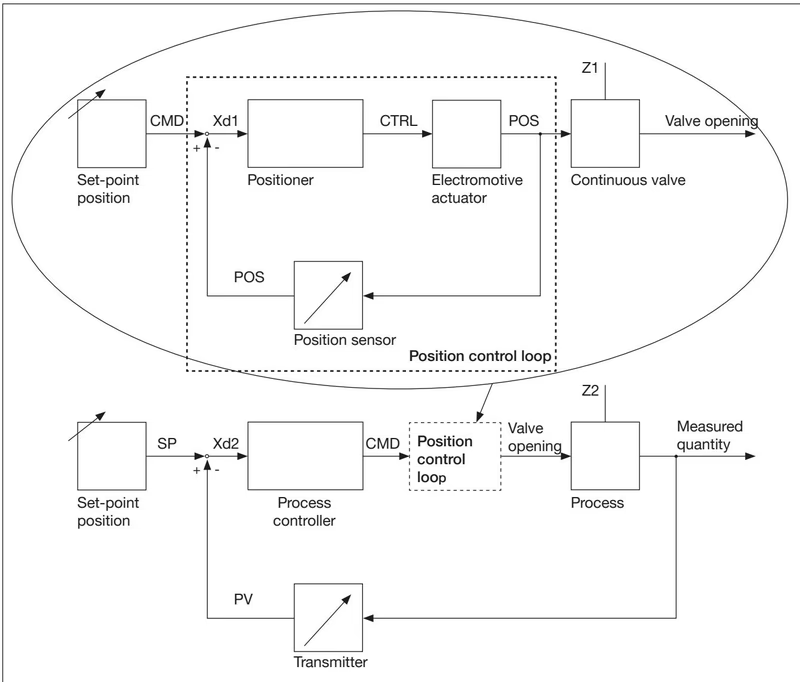
Article 20097830 features integrated process controller electronics operating in cascade control mode. The main control loop runs a configurable PID process algorithm that compares the target process setpoint (SP) against the actual process variable (PV) read from an external sensor. The output of the PID calculation becomes the setpoint position command (CMD) for an inner, auxiliary positioning loop. A contactless, wear-free position sensor tracks the linear actuator position (POS) and feeds it to the inner positioner, which calculates motor steps until control difference Xd2 reaches zero.
The process controller input supports multiple filter stages (0 to 9) to smooth noisy transmitter readings before PID processing:
| Filter Stage Setting | Cut-Off Frequency (Hz) | Low-Pass Damping Effect |
|---|---|---|
| 0 | 10 Hz | Minimum filter effect |
| 1 | 5 Hz | Low filtering |
| 2 | 2 Hz | Standard filtering |
| 3 | 1 Hz | Moderate filtering |
| 4 | 0.5 Hz | Medium filtering |
| 5 | 0.2 Hz | Increased filtering |
| 6 | 0.1 Hz | High filtering |
| 7 | 0.07 Hz | High filtering |
| 8 | 0.05 Hz | Heavy filtering |
| 9 | 0.03 Hz | Maximum filter effect |
All media-wetted components comply with EC Regulation 1935/2004 and GB food standards (variable code PL10), making them suitable for sanitary, beverage, and pure gas processing duties.
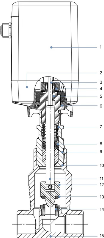
| Item Number | Component Part | Construction Material |
|---|---|---|
| 1 | Housing Cover | Polycarbonate (PC GF10 anthracite) |
| 2 | Housing Base | Polyphenylene sulfide (PPS GF40 black) |
| 3 | Spindle Guide | High-performance polymer |
| 4 | Sliding Washers | High-performance polymer |
| 5 | Guide Piece | Stainless steel 1.4305 |
| 6 | O-Ring | Nitrile rubber (NBR) |
| 7 | Compression Spring | Stainless steel |
| 8 | Spindle Seal | PTFE (filled) / FKM with spring compensation |
| 9 | Pipe | Stainless steel 1.4404 |
| 10 | Body Seal | Graphite |
| 11 | Valve Spindle | Stainless steel 1.4401 |
| 12 | Control Cone | Stainless steel 1.4571 |
| 13 | Seat Seal | PTFE sealing washer |
| 14 | Valve Seat | Stainless steel 1.4571 |
| 15 | Valve Body | Cast stainless steel CF3M / 316L |
The actuator housing can be rotated continuously clockwise by up to 360° after loosening to align cable entries. The valve body must be open during any rotation or disassembly.
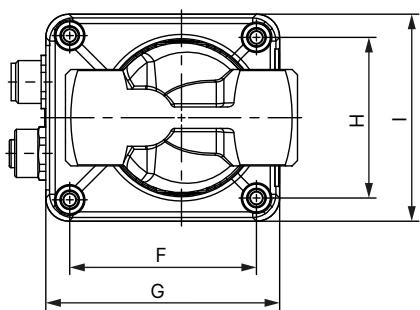
| A | B | C | D | E | F | G | H | I | J |
|---|---|---|---|---|---|---|---|---|---|
| 76 mm | 216 mm | 188 mm | 84 mm | 112 mm | 52 mm | 66 mm | 45 mm | 58 mm | 20 mm |
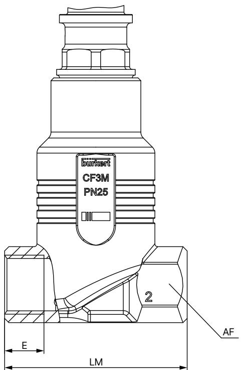
| Port Connection Standard | Thread Size | Thread Depth E (mm) | Face-to-Face Length LM (mm) | Width Across Flats AF (mm) |
|---|---|---|---|---|
| RC (ISO 7-1) | RC 1/2" | 13.2 mm | 65 mm | 27 mm |
| G (DIN ISO 228-1) | G 1/2" | 14.0 mm | 65 mm | 27 mm |
| NPT (ASME B1.20.1) | NPT 1/2" | 13.7 mm | 65 mm | 27 mm |
Article 20097830 features two A-coded M12 circular connectors located on the base of the actuator: one 5-pin plug for digital büS/CANopen communication and power supply, and one 5-pin socket for direct connection of external process sensors.
| Pin | Wire Color (büS Cable) | Pin Assignment | Signal Description |
|---|---|---|---|
| 1 | Shield | Shielding | Cable shield |
| 2 | Red | Supply + | 24 V DC ±10%, max. ripple 10% |
| 3 | Black | GND | Power supply ground |
| 4 | White | CAN_H | Fieldbus CAN high line |
| 5 | Blue | CAN_L | Fieldbus CAN low line |
| Pin | Wire Color (Cable 559177) | Pin Assignment | Signal Specification |
|---|---|---|---|
| 1 | Brown | Sensor Supply + | 24 V DC ±10% auxiliary transmitter power |
| 2 | White | Actual Value Input + | 0/4–20 mA (60 Ω), 0–5/10 V (22 kΩ), or Frequency (5–2000 Hz) |
| 3 | Blue | GND | Sensor ground |
| 4 | Black | GND | Ground bridge to Pin 3 |
| 5 | Grey | Not used | Unassigned |
The Type 3281 series accommodates multiple seat orifices to achieve optimal control rangeability across specific pressure windows. Article 20097830 is built with a 10 mm seat:
| Body Construction | Seat Diameter | Control Mode | Port Connection | Kvs Value (m³/h) | Operating Pressure (bar) |
|---|---|---|---|---|---|
| Globe | 4 mm | Continuous control | 1/2" | 0.57 | 0 to 16 bar(g) |
| Globe | 6 mm | Continuous control | 1/2" | 1.25 | 0 to 16 bar(g) |
| Globe | 8 mm | Continuous control | 1/2" | 1.80 | 0 to 12 bar(g) |
| Globe (20097830) | 10 mm | Continuous control | RC 1/2" | 2.25 | 0 to 7 bar(g) |
| Globe | 15 mm | On/off switching | 1/2" | 4.45 | 0 to 3.5 bar(g) |
| Angle-seat | 15 mm | Continuous control | 1/2" | 3.60 | 0 to 3 bar(g) |
| Angle-seat | 15 mm | On/off switching | 1/2" | 4.55 | 0 to 3.5 bar(g) |
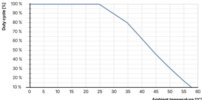
Operating Duty Cycle Limits
The duty cycle represents the actual running time of the stepper motor rather than the powered-on duration of the valve electronics. Because frequent setpoint changes increase motor internal heating, operators must verify thermal limits using the derating diagram. Exceeding recommended duty cycle thresholds reduces actuator service life.
Proper Valve Seat Sizing
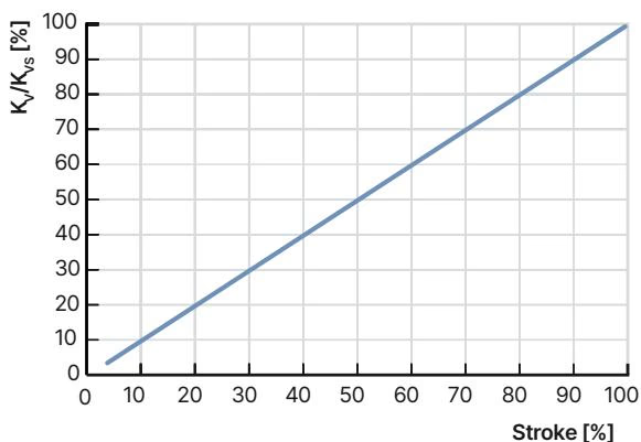
To maintain the intended linear valve characteristic in real piping systems, ensure that at least 25% of the total system pressure drop occurs across the fully open control valve (Δp_valve > 0.25 · Δp_total). Undersized pressure drops distort linear valve curves into non-linear system curves.
Configuration, commissioning, and diagnostics for article 20097830 are executed via the Bürkert Communicator software (Type 8920) running on a Windows PC. Communication hooks directly into the büS/CANopen network via a dedicated USB-büS interface stick.
Key software functions include:
Emergency Fail-Safe Return
Because stepper motor actuators retain their physical position upon sudden loss of power supply, fail-safe emergency homing requires an external capacitive buffer module. The buffer module provides 18 V DC for several seconds during mains interruption, allowing the internal control electronics to drive the valve cone into the pre-configured safety position (SAFEPOS).
| Accessory Description | Article Number |
|---|---|
| USB-büS Interface Set 1 (Type 8923, includes büS stick, terminating resistor, power pack, cables) | 772426 |
| USB-büS Interface Set 2 (Type 8923, includes büS stick, terminating resistor, Y-distributor, 0.7 m cable) | 772551 |
| M12 Shielded Sensor Cable, 5-pin female connector, 2.0 m length (for process actual value input) | 559177 |
| Switched-Mode Power Supply Unit Type 1573 (Phoenix Class 2, 85–240 V AC / 24 V DC, 1.25 A) | 772438 |
| Capacitive Buffer Module Type 1573 (maintains 18 V DC to drive valve to SAFEPOS on power outage) | 773440 |
| Seat Replacement Assembly Tool Insert (for torque tightening of seats 4 to 10 mm to 20 ±3 Nm) | 625604 |
Explore similar products in our catalog