


PN25

Burkert 20100064 (Type 2101) is a pneumatically operated 2/2-way globe valve (DN25, weld end) in stainless steel with normally closed function A, PTFE seat seal, and 0–25 bar operating pressure.
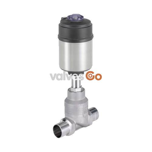
Burkert 20100064 (Type 2101) is a pneumatically operated 2/2-way globe valve configured for on/off isolation of liquid and gaseous media. Built with a cast stainless steel body (316L) and a polyphenylene sulphide (PPS) piston actuator, this specific unit provides a nominal orifice diameter of DN 25 (25 mm seat diameter) and welded pipe ends conforming to ISO 4200, DIN 11866 Series B, and DIN EN ISO 1127 (outer diameter 33.7 mm, inner diameter 29.7 mm, wall thickness 2.0 mm). Operating under control function A (normally closed by spring force), the valve shuts off tight against media flow introduced below the seat, delivering a flow factor Kv of 13 m³/h and an operating pressure range of 0 to 25 bar (PN 25 / Class 150).
Engineered for high hygienic and industrial standards, this execution is CIP and SIP capable, supports steam sterilization, and is cleaned oil- and grease-free for oxygen service according to standard DIS 1000020797. The spindle is sealed via self-adjusting PTFE V-rings with spring compensation, and the valve disc incorporates a stainless steel swivel plate with a PTFE seat seal to maintain high seat tightness without sticking.
Type 2101 comprises a pneumatic piston actuator mounted directly onto a 2-way globe valve body. The mechanical link between actuator piston and closing element is established through a stainless steel spindle guided in PEEK bushings. Spring force (control function A) acts downward through the spindle to press the swivel plate against the screwed-in valve seat.
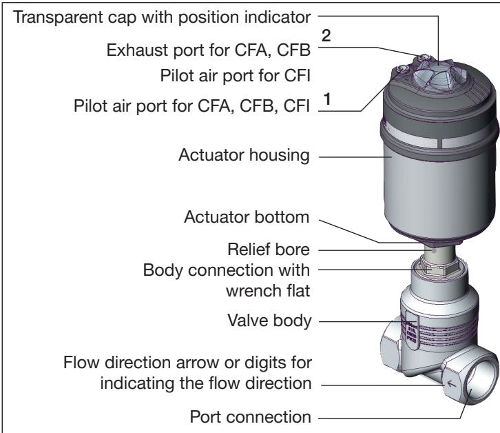
In this configuration, process media flows below the seat. Medium pressure acts on the underside of the swivel plate, assisting the opening motion when compressed air is supplied to pilot port 1. When the pilot chamber is vented, heavy-duty internal springs drive the swivel plate closed against the medium stream, eliminating water hammer risks typical of flow-above-seat configurations on liquid lines.

Definition of DN
In Burkert Type 2101 documentation, DN designates the nominal diameter of the internal orifice seat (25 mm for article 20100064), rather than the pipeline connection size.
| Specification Parameter | Value / Material |
|---|---|
| Valve Type | Type 2101 2/2-way globe valve |
| Burkert Article Number | 20100064 |
| Control Function | CFA (Normally closed in rest position by spring force) |
| Flow Direction | Below seat (closing against medium flow) |
| Nominal Diameter (DN) | DN 25 (Seat ø 25 mm) |
| Kv Value (Water) | 13 m³/h |
| Body Material | Stainless steel 316L |
| Actuator Housing Material | Polyphenylene sulphide (PPS) |
| Spindle Material | 1.4401 / 1.4404 stainless steel |
| Spindle Guide | PEEK (for sizes up to DN 65) |
| Swivel Plate Material | Stainless steel with PTFE seal insert |
| Packing Gland Seals | Self-adjusting PTFE V-rings with spring compensation |
| Process Connection | Weld end: ISO 4200 / DIN 11866 B / DIN EN ISO 1127 |
| Weld Dimensions | Outer ø 33.7 mm, Inner ø 29.7 mm, Wall thickness 2.0 mm |
| Operating Pressure Range | 0.00 bar to 25.00 bar (PN 25 / Class 150) |
| Pilot Pressure Range | 5.0 bar to 10.0 bar |
| Medium Temperature Range | -10 °C to +60 °C (device specific per datasheet) |
| Ambient Temperature Range | -10 °C to +60 °C |
| Enclosure Rating | IP67 per IEC 529 / EN 60529 |
| Oxygen Cleanliness | Yes, oil- and grease-free per DIS 1000020797 |
Operating pressure limits must be derated according to the applicable piping standard when process temperatures exceed room ambient:
| Temperature Range | PN 25 (DIN EN 12516-1) | Class 150 (ASME B16.5 / B16.34) | JIS B 2220 10K |
|---|---|---|---|
| -10 °C to +38/+50 °C | 25.0 bar | 19.0 bar | 14.0 bar |
| +100 °C | 24.5 bar | 16.2 bar | 14.0 bar |
| +150 °C | 22.4 bar | 14.8 bar | 13.4 bar |
| +200 °C | 20.3 bar | 13.7 bar | 12.4 bar |
| +230 °C | 19.0 bar | 12.7 bar | 11.7 bar |
Pressure Equipment Directive Limits
According to the Pressure Equipment Directive (PED), specific pressure limitations apply for compressible fluids of Group 1 (hazardous gases and vapors): DN65 is capped at 15 bar, DN80 at 12.5 bar, and DN100 at 10 bar.
The valve can be installed in any orientation, though an upright actuator orientation is recommended for optimal drainability and seal longevity. Before fitting, piping lines must be flushed clean of welding residue, scale, and foreign matter.
When welding the valve body into the pipeline, the actuator and any attached control unit must be detached from the stainless steel body to protect polymer housings and elastomer/PTFE seals from heat damage.
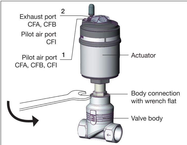
| Connection Size (DN) | Body Tightening Torque |
|---|---|
| DN 15 | 45 ± 3 Nm |
| DN 20 | 50 ± 3 Nm |
| DN 25 (Article 20100064) | 60 ± 3 Nm |
| DN 32 / DN 40 | 65 ± 3 Nm |
| DN 50 | 70 ± 3 Nm |
| DN 65 | 100 ± 3 Nm |
| DN 80 | 120 ± 5 Nm |
| DN 100 | 150 ± 5 Nm |
Spring Tension Hazard
The actuator housing contains a preloaded internal spring under mechanical tension. Never attempt to disassemble or pry open the actuator housing; violent release of the internal spring can cause severe physical trauma.
Lubricant Compatibility
Article 20100064 is prepared for oxygen applications. In oxygen or purity-critical systems, only use certified lubricants compatible with oxygen. Inappropriate greases present acute combustion or explosion risks.
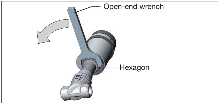
The actuator body can be steplessly rotated 360° to orient pneumatic supply lines away from structural interferences. Pressurize pilot port 1 with 5 bar air (keeping the valve open), engage the body connection hexagon with an open-end wrench, and rotate the actuator counterclockwise (viewed from below) to the target orientation.
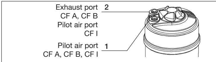
Pneumatic pilot air is connected to port 1 using standard 6/4 mm or 1/4" hose connections. On single-acting CFA valves, venting occurs through port 2, where an unattached silencer is supplied to minimize acoustic noise. In corrosive ambient environments, exhaust port 2 can be ducted away to prevent atmospheric contaminants from entering the actuator chamber.
The intermediate valve tube features an external relief bore located between the actuator seal and the spindle packing. This bore provides immediate visual indication of packing gland wear or seat bypass.
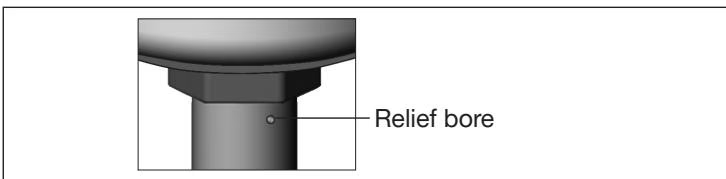
Relief Bore Sensor Option
Under option code NA99, an adapter can be threaded into the relief bore (M4x0.35 thread adapted to M5x0.8) to connect automated leakage detectors. Do not attach closed vessels or allow back pressure to develop in this port, as escaping media forced into the actuator can cause total device failure.
Under regular operational parameters, the Type 2101 actuator is maintenance-free. Visual inspections should regularly confirm body joint tightness and check the relief bore for fluid weeping.
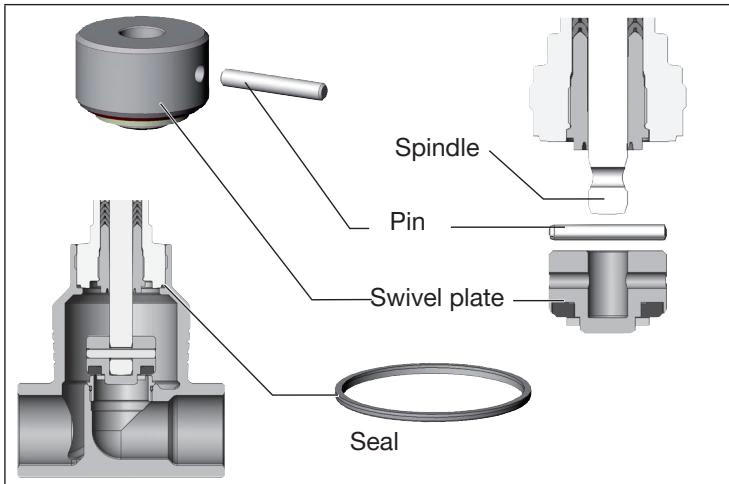
When seat bypass occurs due to particulate damage or cycle wear, the swivel plate and screwed-in seat ring can be replaced independently.
| Valve Seat Orifice | Seat Assembly Torque |
|---|---|
| DN 15 | 20 ± 3 Nm |
| DN 20 | 28 ± 3 Nm |
| DN 25 (Article 20100064) | 40 ± 5 Nm |
| DN 32 | 65 ± 5 Nm |
| DN 40 | 85 ± 8 Nm |
| DN 50 | 120 ± 8 Nm |
| DN 65 | 150 + 10 Nm |
| DN 80 | 180 + 10 Nm |
| DN 100 | 220 + 10 Nm |
| Spare Part Kit Designation | Included Components | Order Number |
|---|---|---|
| Valve Set DN 25 (PTFE) | Swivel plate with PTFE seal, retaining pin, body seal | 160 737 |
| Valve Seat Set DN 25 | Coated valve seat ring, O-ring, body seal | 262 170 |
| Packing Gland Seal Set (10 mm spindle) | Support ring, 7 chevron V-rings, thrust collars, spring, guide, lubricant | 216 433 |
| Seat Assembly Key DN 25 | Tool insert for seat extraction and torquing | 652 606 |
| Modified Socket Wrench (10 mm spindle) | Socket wrench AF 19 for packing gland spindle guide | 683 221 |
| Symptom | Root Cause | Corrective Action |
|---|---|---|
| Actuator fails to switch | Pilot air connected to wrong port | For CFA, verify pilot pressure is applied strictly to port 1. |
| Pilot pressure below minimum limit | Verify pilot pressure is at least 5.0 bar (max 10 bar). | |
| Operating medium pressure too high | Compare line pressure against type label limits (max 25 bar). | |
| Valve leaks across the seat | Foreign particulate trapped in seat | Disassemble and install upstream dirt trap (DIN EN 161 strainer). |
| PTFE seat seal worn or deformed | Install replacement valve set (order no. 160 737). | |
| Medium leaking from relief bore | Spindle packing gland worn | Replace packing gland seal kit (order no. 216 433) using tool 683 221. |
For versions operating under ATEX/IECEx mechanical certification EPS 18 ATEX 2 008 X / IECEx EPS 18.0007 X (Ex h IIC T4...T2 Gb / Ex h IIIC T135 °C...T300 °C Db), equipotential bonding is mandatory. Connect the stainless steel valve body to the pipe grounding system and ground conductive actuator components via dedicated grounding strap clamps. Wipe exterior surfaces with damp or antistatic cloths only to avoid electrostatic discharge hazards.
Explore similar products in our catalog



