

PN16

Burkert Type 8640 modular valve island (SKU 20100267) for pneumatics. Features 2 to 24 valve functionalities, DIN-rail mounting, and AirLINE Quick compatibility.
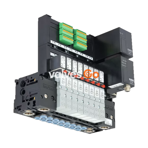
Burkert Type 8640 modular valve island system is designed to solve diverse and complex control problems through its systematic modular construction and combination of pneumatic and electrical interfaces. By putting together a row of pneumatic modules with different numbers of valves, 2 to 24 valve functionalities may be realized on one valve unit. Electrical connectivity is achieved by either fieldbus interfaces, common connection (parallel connection technique), or multipin interfaces. Bodies and connection modules are made of high-quality plastic (polyamide) and are assembled using built-in snap connectors.

The Type 8640 system supports multiple pilot valve types (including Type 6524, 6525, 0460, 6526, 6527, and 5470) with varying station widths.
| Feature | Specification |
|---|---|
| Width per station | 11 mm, 16.5 mm, 19 mm |
| Number of valve slots | Max. 24 (Max. 12 for impulse and double valves with multipol/fieldbus) |
| Pressure range | Vac...10 bar (Overpressure to atmospheric pressure) |
| Operating voltage | 24 V DC (±10% voltage tolerance) |
| Nominal operating mode | Continuous operation (100% duty cycle) |
| Operating medium | Oil-free or lubricated compressed dry air, neutral gases (5 μm filter recommended) |
| Compressed air quality | ISO 8573-1: 2010, Class 7.4.4 |
| Degree of protection | IP20 (IP65 in closed control cabinets) |
| Ambient temperature | 0 °C...+ 55 °C (0 °C...+ 50 °C when using Type 0460/0461) |
AirLINE Quick considerably reduces the use of components in the control cabinet. With the AirLINE Quick Adapter, the valve terminal is adapted directly to the control cabinet floor or control cabinet wall.
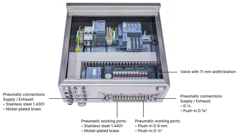
INFO
Type 0460 valves cannot be installed with AirLINE Quick due to their size.
For configurations utilizing the 4/2-way valve, it is possible to convert the unit to a 3/2-way valve depending on the desired circuit function by closing port 2 or port 4 with a stopper.
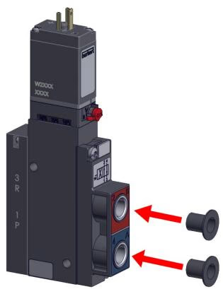
| Port 2 | Port 4 | Circuit function |
|---|---|---|
| closed | open | C (Normally closed) |
| open | closed | D (Normally open) |
DANGER
Risk of injury due to high pressure and escaping medium. Switch off the pressure before working on the device or system. Vent or drain the pipes. Risk of injury due to electric shock. Switch off voltage before working on the device or system. Secure against reactivation.
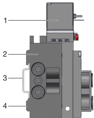
Standard rail installation:
Wall installation: Fasten the valve block directly to the wall with M4 screws.
Valves are delivered fully assembled. If the location of the solenoid of the pilot valve is not suitable for installation, the solenoid can be rotated 180°.
WARNING
Danger of electric shock if the coil is installed incorrectly. When installing, make sure that the coil is firmly seated on the valve body so the protective conductor connection of the coil is connected to the valve body.
Push the hose lines into the push-in connections of the solenoid valves until they come to a stop. Use PTFE tape or elastomer seal for sealing the threaded connection. Connect the supply and working lines to the valve block.
Requirements for hose lines:
If you encounter leakage or retention problems when installing pneumatic hoses in the push-in connectors, ensure the appropriate combination of hose material (polyamide or polyurethane) is used. Cut the hose straight; cutting it diagonally adversely affects the holding force. Press the hose into the push-in connector with sufficient force so that it is held correctly by the claws. If the problem persists, support sleeves can be used to increase the stability and tightness of hoses, particularly for softer polyurethane (PU) hoses.
TIP
If continuous operation is interrupted, a minimum activity of 1-2 switching operations per day is recommended for the duration of the downtime to ensure functional reliability.
Explore similar products in our catalog


