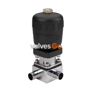
Type 2032

Burkert 20106862 Type 2934 manually operated T-diaphragm valve. Features a DN 25 welded connection, PTFE/EPDM diaphragm, and stainless steel block body for hygienic applications up to 10 bar.
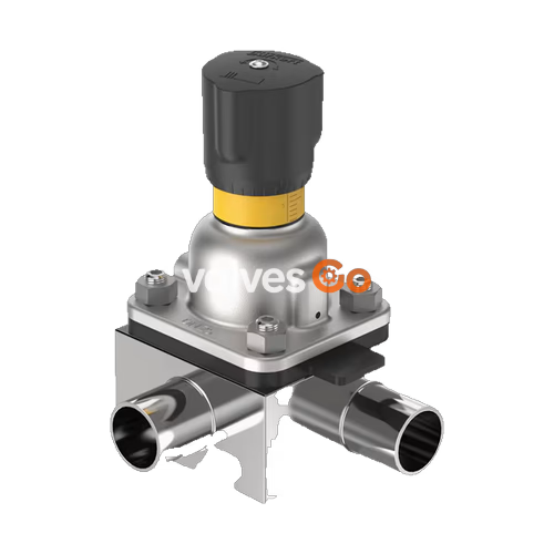
Burkert 20106862 Type 2934 manually operated diaphragm valve consists of a manually operated actuator, a PTFE/EPDM diaphragm, and a T-valve body. The manual actuator with a PPS (Polyphenylene sulphide) handwheel is available with a PPS diaphragm bonnet and ensures use in hygienic or aggressive ambient conditions. The flow-optimised stainless steel block valve body with minimum dead space enables high flow values and a wide range of possible applications. The actuator has a compact, autoclavable design and is equipped with an integrated visual position indicator and a single min-stroke limiter (closing limiter).
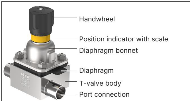
The Type 2934 diaphragm valve is designed to meet stringent hygienic and safety requirements:
Explosion Hazard in Potentially Explosive Areas
When using the device in potentially explosive areas, ensure proper grounding of the actuator and valve body to prevent electrostatic charging. Only use media with appropriate conductivity limits as specified in IEC 60079-32-1.
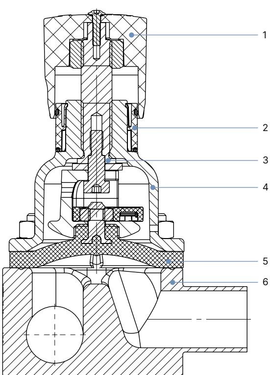
| No. | Element | Material |
|---|---|---|
| 1 | Handwheel | Polyphenylene sulphide (PPS) |
| 2 | Visual position indicator | Polyamide (PA) / Stainless steel 1.4305 |
| 3 | Valve spindle | Stainless steel 1.4305 |
| 4 | Diaphragm bonnet | Polyphenylene sulphide (PPS) |
| 5 | Diaphragm | PTFE with EPDM backing membrane |
| 6 | Valve body | Stainless steel block material 1.4435 (DIN EN 10088) / 316L (ASTM A479/A479M) |
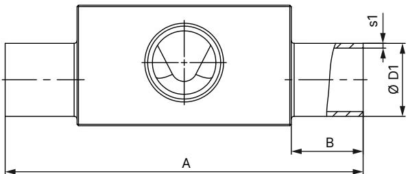
Note: Dimensions in mm, unless otherwise stated. The specific SKU 20106862 features a DN 25 (25.4x1.65) welded connection according to ASME BPE / DIN 11866 Series C.
The values are valid for valve bodies made from stainless steel block material. For the PTFE/EPDM diaphragm (Diaphragm size 20), the maximum permitted medium pressure is 10 bar.
Excessive torque can shorten the service life of the diaphragm. A tolerance of +10% applies to the tightening torques specified.
| Diaphragm Size | Maximum Static Operating Pressure | Tightening Torque (PTFE/EPDM) |
|---|---|---|
| 20 | 10 bar | 3 Nm |
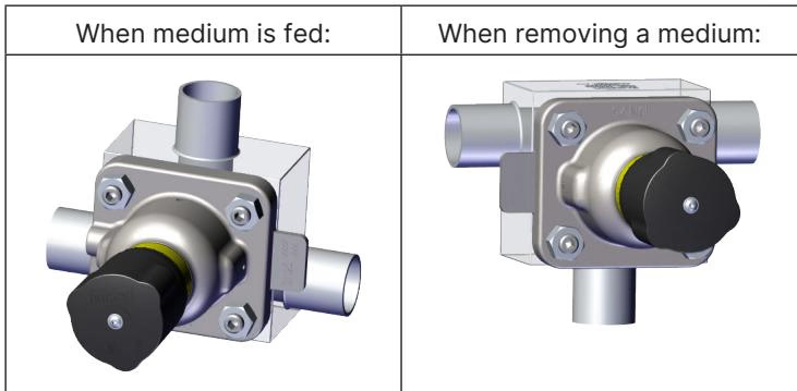
The following installation positions are recommended for the installation of the T-valves in circular pipelines to ensure proper self-draining:
Welding Instructions
To prevent damage, dismantle the actuator and diaphragm before welding the valve body into the pipeline. After welding, clean the valve body thoroughly before reassembling the diaphragm and actuator. Tighten the fastening screws crosswise in 3 stages (approx. 1/3, 2/3, and 3/3 of the tightening torque).
When used in accordance with the operating instructions, the actuator of the diaphragm valve is maintenance-free.
Explore similar products in our catalog