

PN16

BURKERT 20107356 (Type 8640) is a 12-bank modular pneumatic valve island featuring 19 mm station width, Sub-D 25-pin multi-pole interface, G 1/4 supply ports, D6 push-in bottom working connections, and 2 to 8 bar pressure range.
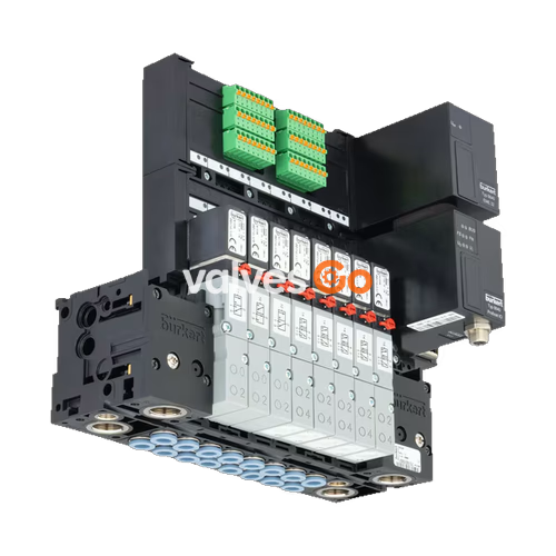
BURKERT 20107356 (Type 8640) is a 12-bank modular pneumatic valve island configured with a 19 mm station width and multi-pole electrical connectivity via a 25-pin Sub-D connector. Built on modular MP05 pneumatic base rails with high-performance polyamide (PA) bodies and NBR seals, this assembly integrates 12 valve slices executing 3/2-way pneumatic switching functions. Compressed air supply and exhaust are routed through common G 1/4 connection blocks, while working outlets are arranged as D6 mm push-in connections located on the underside of each valve station.
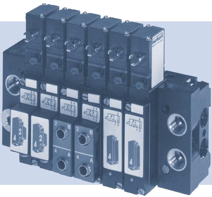
Operating within a nominal pressure span of 2.00 bar to 8.00 bar, the unit provides a standard nominal flow rate ($Q_{Nn}$) of 300 l/min per valve station. The multi-pole interface consolidates the 24 V DC control signals of all 12 solenoid coils into a central Sub-D 25 plug, eliminating individual point-to-point field wiring inside the control cabinet. The assembly conforms to ingress protection class IP54, with capability up to IP65 inside enclosed industrial control cabinets.
Modular System Configuration
Type 8640 modular valve islands allow flexible staging of pneumatic and electrical modules. While the 8640 series accommodates 11 mm and 16.5 mm widths, article 20107356 is configured specifically with 19 mm wide stations utilizing MP05 pneumatic base elements and Type 5470 rocker pilot valve technology.
| Specification Parameter | Value / Detail |
|---|---|
| Article Number | 20107356 |
| Valve Island Type | 8640 |
| Number of Valve Stations | 12-bank |
| Width per Station | 19 mm |
| Switching Function | 3/2-way valve function |
| Supply Connections 1 (P), 3 (R) | G 1/4 |
| Working Outlets 2 (B), 4 (A) | Push-in coupling ∅ 6 mm, bottom exit |
| Nominal Pressure Range | 2.00 bar to 8.00 bar |
| Pilot Pressure Requirement | 2 to 10 bar (at least 70% of operating pressure) |
| Pressure Differential | Port 1 to Port 3 minimum 2 bar |
| Medium Temperature | 0 °C to +50 °C |
| Ambient Temperature | 0 °C to +55 °C |
| Operating Voltage | 24 V DC (±10% tolerance, residual ripple 1 Vss) |
| Nominal Coil Power | 1 W to 2 W per valve station |
| Nominal Operating Mode | Continuous operation (100% duty cycle) |
| Medium Quality | Filtered compressed air (particle size max. 10 μm, 5 μm recommended), neutral gases |
| Compressed Air Standard | ISO 8573-1:2010, Class 7.4.4 |
| Protection Class | III according to VDE 0580 |
| Degree of Protection | IP54 (up to IP65 in closed control cabinet) |
| Installation Arrangement | DIN rail EN 50022 (35 × 7.5 mm / 35 × 15 mm) or wall mounting |
Type 8640 valve blocks are constructed by interlocking multi-block pneumatic base modules between left and right connection units using snap-fit latch hooks. Each joint between adjacent base modules is sealed with two elastomeric O-rings in the integrated supply channel 1 (P) and exhaust channel 3 (R).
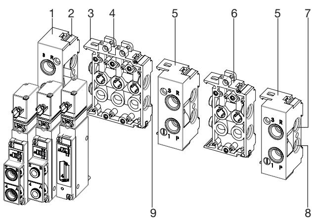
| Item | Module Component |
|---|---|
| 1 | Left connection module |
| 2 | Latch tab |
| 3 | Latch hook |
| 4 | Base modules (3-fold) |
| 5 | Right connection module |
| 6 | Base modules (2-fold) |
| 7 | Exhaust channel 3 (R) |
| 8 | Supply channel 1 (P) |
| 9 | Sealing O-ring |
Assembly begins with the left pneumatic connection module. Subsequent base units snap securely into place by engaging the lower latch hooks into the receiving grooves of the preceding block, followed by pressing upward to lock the upper latch hook. Each individual valve slice mounts to the base module using two screws tightened to a torque of 0.6 ±0.1 Nm, seated over three sealing O-rings positioned in the rear recess of the valve body.
Each 19 mm station utilizes a Type 5470 pneumatic valve driven by an integrated Type 6106 rocker pilot valve. A tilting bearing armature inside the pilot stage oscillates without friction, eliminating mechanical wear and operating without base lubrication.
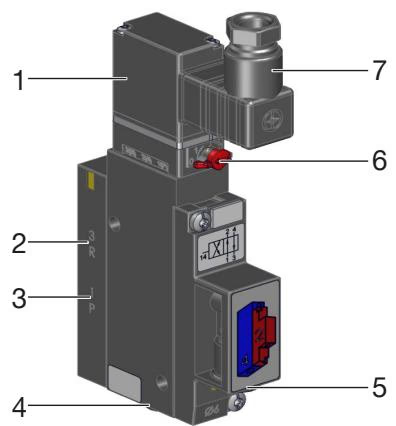
| Item | Designation |
|---|---|
| 1 | Pilot valve Type 6106 |
| 2 | Exhaust port 3 |
| 3 | Pressure supply port 1 |
| 4 | Working port 4 |
| 5 | Working port 2 |
| 6 | Manual override |
| 7 | Electrical interface / cable connection |
Each valve is equipped with a lockable manual override for commissioning and testing. Actuation is carried out by pressing the override mechanism and turning it 90° clockwise until it hits the internal stop. In this position, the manual override remains mechanically locked and does not spring back automatically.
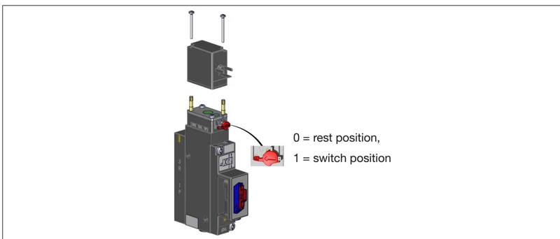
Manual Override Operational Restriction
Operate the manual override only when electrical power is switched off. Unlock the manual override completely before restoring electrical control to prevent valve failure or unintended actuator movement.
Article 20107356 delivers 3/2-way functionality across its 12 valve stations. The underlying Type 5470 architecture can be configured between 4/2-way and 3/2-way modes depending on which working port is blanked with a stopper.
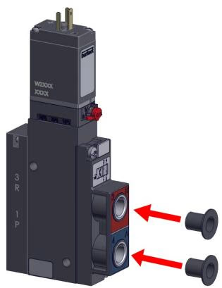
| Port 2 Status | Port 4 Status | Resulting Circuit Function | Operating State in Rest Position |
|---|---|---|---|
| Closed (stopper) | Open | Function C (3/2-way NC) | Supply port 1 (P) closed, working port 4/2 open to exhaust 3 (R) |
| Open | Closed (stopper) | Function D (3/2-way NO) | Supply port 1 (P) open to working port, exhaust port 3 (R) closed |
| Open | Open | Function G (4/2-way) | Port 1 connected to port 2; port 4 connected to port 3 |
Pneumatic supply 1 (P) and exhaust 3 (R) feature G 1/4 internal threads. Working lines connect directly to the bottom ∅ 6 mm push-in couplings. Hoses must possess a minimum hardness of 40 Shore D according to DIN 53505 / ISO 868 and an outer diameter conforming to DIN 73378.
Push-In Fitting Reliability
Cut pneumatic hoses strictly perpendicular and deburr before insertion. Hoses must be pushed past initial resistance until they hit the internal stop. When using flexible polyurethane (PU) tubing, install internal support sleeves (ID 20099400) to ensure high retention forces and leak-tight seating.
According to DIN ISO 14743:2020, pneumatic connections must withstand specified tensile forces during operation:
| Hose Outer Diameter (OD) | Polyamide (PA) Minimum Tensile Force | Polyurethane (PU) Minimum Tensile Force |
|---|---|---|
| 3 mm (1/8") | 60 N | 25 N |
| 4 mm (5/32") | 70 N | 50 N |
| 6 mm (1/4") | 120 N | 100 N |
| 8 mm (5/16") | 170 N | 150 N |
| 10 mm (3/8") | 250 N | 200 N |
| 12 mm (1/2") | 300 N | 200 N |
Thread tightening torques for pneumatic port connections:
| Port Size | Port Designation | Recommended Torque | Maximum Permissible Torque |
|---|---|---|---|
| G 1/4 / NPT 1/4 | Supply 1 (P), Exhaust 3 (R/S) | 4 to 7 Nm | 20 Nm |
| G 1/8 / NPT 1/8 | Working connections (A/B) | 3 to 6 Nm | 7 Nm |
BURKERT 20107356 mounts either to standard DIN rails or directly onto a flat mounting plate inside a control cabinet.
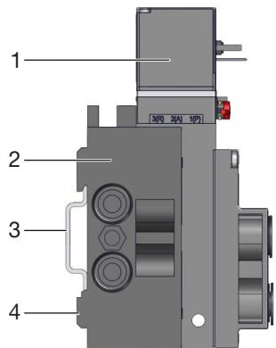
| Item | Mounting Element |
|---|---|
| 1 | Electrical connection module (Sub-D 25-pin) |
| 2 | Wall mounting flange |
| 3 | Standard rail EN 50022 (35 × 15 mm or 35 × 7.5 mm) |
| 4 | Pneumatic connection module |
For DIN rail mounting, hook the upper channel of the valve block over the top edge of the EN 50022 rail, snap the lower clamping brackets into position, and tighten the clamping screws. For direct wall mounting, secure the valve island using M4 screws through the integrated side brackets.
| Fault Symptom | Probable Cause | Corrective Action |
|---|---|---|
| Valves do not switch | Operating voltage absent or below tolerance | Check Sub-D 25 wiring; confirm 24 V DC (±10%) at coil terminals. |
| Valves do not switch | Manual override engaged | Rotate manual override 90° counter-clockwise to zero position. |
| Valves do not switch | Insufficient supply pressure | Ensure system pressure is ≥ 2.0 bar and pilot pressure differential is maintained. |
| Delayed switching or continuous blow-off at exhaust | Insufficient air volume / pressure dip | Verify supply line cross-section; size upstream regulators and filters adequately. |
| Delayed switching or blow-off | Valve not in home position during pressure rise | Pressurize the valve manifold before applying electrical control signals. |
| Delayed switching | Silencer restriction / back-pressure | Inspect exhaust silencers on port 3 (R); clean or replace blocked elements. |
| Delayed switching | Particulate contamination in pilot stage | Apply pulsed air bursts to exhaust ducts to flush debris, or replace pilot valve. |
| External leakage between modules | Damaged or displaced O-rings | Disassemble joint, replace MP05 seals, ensure light lubrication, and re-engage snap tabs. |
| External leakage at valve base | Missing or pinched flat seals | Check valve base seating; ensure three O-rings are positioned and tighten screws to 0.6 Nm. |
Explore similar products in our catalog


