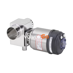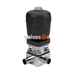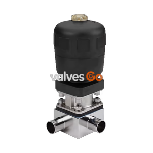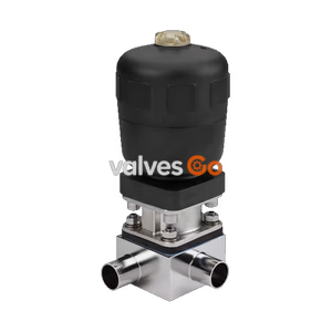
Type 2032

BURKERT 20108541 Type 2933 is a manually operated 2/2-way diaphragm valve with Hastelloy C22 body, DN 15 ASME BPE welded ports, PTFE/EPDM seal, autoclavable PPS handwheel, and 0-10 bar operating pressure.
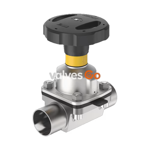
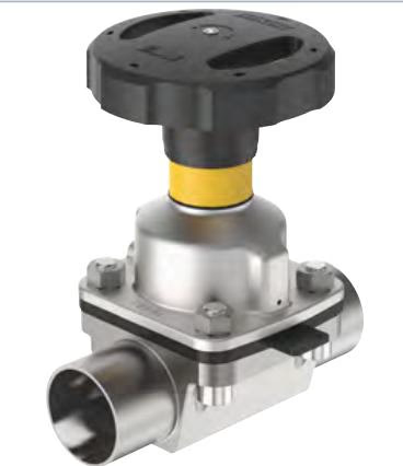
BURKERT 20108541 (Type 2933) is a manually operated 2/2-way diaphragm valve engineered for zero deadleg shut-off duties in hygienic, sterile, and corrosive chemical processes. Built with a Hastelloy C22 (material 2.4602) valve body, this model features welded line connections conforming to ASME BPE and DIN 11866 Series C with port dimensions of 12.7 x 1.65 mm (DN 15, NPS 1/2). Fluid isolation is achieved with a diaphragm size 8 seal comprised of PTFE with an EPDM backing diaphragm, ensuring non-contaminating operation across a static medium pressure range from 0 to 10 bar (PN 10, Class 150). The valve operates continuously across medium temperatures from -10 °C to +130 °C and tolerates steam sterilisation up to +140 °C for 60 minutes.
Equipped with a compact manual actuator, the valve utilizes a stainless steel diaphragm bonnet and a 35 mm diameter polyphenylene sulphide (PPS) handwheel (size T, 1.5 mm spindle pitch per rotation). The manual assembly incorporates an integrated optical visual position indicator located beneath the handwheel and an adjustable mechanical minimum stroke limiter that protects the PTFE diaphragm against overcompression during closing. Both CIP and SIP cleaning procedures are fully supported. All wetted polymer elements meet USP Class VI, FDA Code of Federal Regulations, and EC Regulation 1935/2004 requirements, backed by manufacturer test certificate EN 10204 3.1 and factory certification EN 10204 2.1.
| Attribute | Source-Supported Specification |
|---|---|
| Valve Type | 2933 (Basic 2/2-way manually operated shut-off valve) |
| Article Number | 20108541 |
| Diaphragm Size | 8 |
| Port Nominal Size | DN 15 (NPS 1/2) |
| Port Outer Diameter x Wall Thickness | 12.7 x 1.65 mm |
| Connection Standard | Welded connection to ASME BPE / DIN 11866 Series C |
| Body Material | Hastelloy C22 (2.4602) |
| Bonnet Material | Stainless steel |
| Handwheel Material | PPS (polyphenylene sulphide) |
| Diaphragm Material | PTFE with EPDM backing diaphragm (code EA) |
| Operating Pressure Range | 0 bar to 10 bar (static) |
| Pressure Ratings | PN 10 (DIN EN 1333), Class 150 (DIN EN 1759) |
| Medium Temperature Range | -10 °C to +130 °C (steam sterilisation max. +140 °C for 60 min) |
| Ambient Temperature Range | -10 °C to +130 °C (short-term up to +150 °C), autoclavable |
| Flow Coefficient (Kv) | 1.9 m³/h (water at +20 °C, inlet 4 bar, outlet 3 bar) |
| Surface Roughness | Ra ≤ 0.38 µm to Ra ≤ 1.6 µm |
| Stroke Limitation | Single min-stroke limiter (closing limiter via internal nut) |
| Position Feedback | End position feedback sensor without (optional M5 sensor port) |
| Cleaning Capabilities | CIP capable: Yes; SIP capable: Yes |
| Product Identification | Data matrix code, physical laser etching |
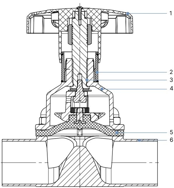
| Item No. | Component | Source Material |
|---|---|---|
| 1 | Handwheel | Polyphenylene sulphide (PPS) (optional 1.4308 stainless steel) |
| 2 | Visual position indicator | Polyamide (PA), Stainless steel 1.4305 |
| 3 | Valve spindle | Stainless steel 1.4305 |
| 4 | Diaphragm bonnet | Stainless steel 1.4308 (optional PPS) |
| 5 | Diaphragm | PTFE with EPDM backing (EA) (alternatives: EPDM AD, Advanced PTFE EU, GYLON/EPDM ER) |
| 6 | Valve body | Hastelloy C22 (2.4602) for article 20108541 |
INFO
Chemical compatibility across aggressive process media can be cross-referenced via the Bürkert resistApp database prior to deploying alternative materials.
Manual actuator dimensions correspond to diaphragm size 8 (handwheel size T):
| Diaphragm Size | Handwheel Size Code | Handwheel Designation | Handwheel Diameter ∅ B [mm] | Open Height H1 [mm] | Closed Height H2 [mm] | Spindle Pitch [mm/rev] |
|---|---|---|---|---|---|---|
| 8 | T | Tiny | 35 | 54 | 49 | 1.5 |
Rotating the PPS handwheel counterclockwise draws the internal spindle upward, opening the flow passage and gradually revealing the yellow visual position indicator positioned on the diaphragm bonnet. Turning the handwheel clockwise closes the valve orifice.
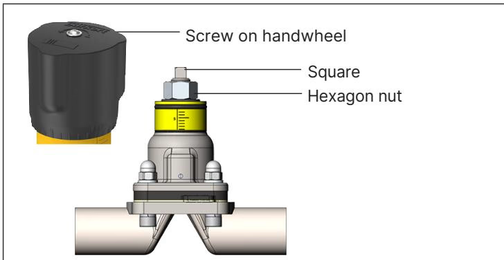
The Type 2933 manual actuator contains an internal stroke limiter that prevents excessive compression force on the diaphragm seal:
WARNING
Do not thread the hexagon nut across the square spindle profile. The minimum stroke limiter is designed solely for setting within the 0% to 25% valve stroke opening range.
Manual operation requires specific handwheel torques to establish tight shut-off without shortening diaphragm operating life. A tolerance of +10% applies to all source torque ratings.
| Diaphragm Size | Medium Pressure [bar] | Static Tightening Torque [Nm] | Dynamic Tightening Torque [Nm] | | :--- | :--- | :--- | :--- | :--- | | 8 | 10 | 1.1 (PTFE) / 0.6 (EPDM) | 1.2 (PTFE) / 0.9 (EPDM) |
Static tightness defines zero seat leakage with the valve closed and pressure applied to one port. Dynamic tightness defines closure against media flowing through the open orifice until the designated shut-off torque is reached.
Installation position is universal, though orientation with the actuator facing upright is preferred. When installed for self-draining performance, the valve body must be positioned according to the drain angle specified for DN 15 ASME BPE welded bodies (12.7 x 1.65 mm):
DANGER
Depressurize and completely drain or vent the piping system prior to beginning any mechanical installation or dismantling.
To prevent permanent thermal damage to internal elastomers:
| Diaphragm Size | Body Material Type | EPDM / FKM Fastening Torque [Nm] | PTFE / Advanced PTFE Fastening Torque [Nm] |
|---|---|---|---|
| 8 | VS (Hastelloy / Forged), VG, Plastics | 2.0 | 2.5 |
Diaphragm inspection intervals depend on media temperature, abrasiveness, and switching frequency. Check the bonnet relief bore regularly for escaping fluid. After the initial in-line steam sterilisation cycle, retighten the four body fastening bolts crosswise to 2.5 Nm.
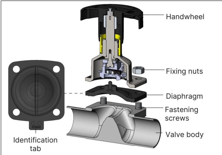
Diaphragm size 8 utilizes a buttoned connection method on both PTFE and elastomeric diaphragms:
| Diaphragm Size | Diaphragm Material | Bürkert Article Number | Material Identification Tab Code |
|---|---|---|---|
| 8 | PTFE/EPDM (EA) | 20093068 | PTFE L11 |
| 8 | Advanced PTFE/EPDM (EU) | 20093078 | PTFE L12 |
| 8 | EPDM (AD) | 688421 | EPDM E04 |
| 8 | FKM (FF) | 677684 | FKM F01 |
| 8 | GYLON/EPDM laminate (ER) | 693175 | PTFE L08 |
All contact polymers used in article 20108541 comply with major international hygienic directives:
When equipped under variable code PX51, the manual actuator is certified as a non-electrical Category 2 mechanical device for explosive gas and dust atmospheres (Zone 1/21 and Zone 2/22):
| Temperature Class | Maximum Surface Temperature | Permissible Ambient Temperature | Maximum Medium Temperature |
|---|---|---|---|
| T4 | +135 °C | -40 °C to +100 °C | +125 °C |
| T3 | +200 °C | -40 °C to +130 °C | +185 °C |
| T2 | +300 °C | -40 °C to +130 °C | +285 °C |
TIP
Conductive grounding of both the Hastelloy body and the actuator is mandatory when deploying in hazardous areas to prevent static discharge.
Explore similar products in our catalog