PN16

Burkert Type 8653 (SKU 20108823) AirLINE Field module optimized for process automation. Features IO-Link interface, LC display diagnostics, IP65/67 protection, and 4 valve ports.
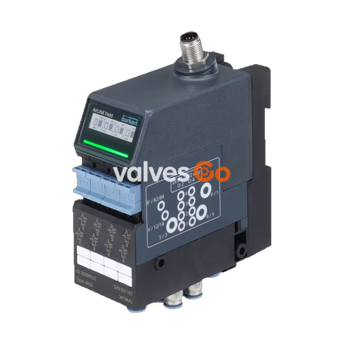
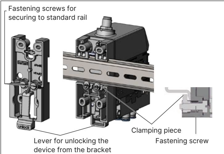
Burkert Type 8653 AirLINE Field valve island has been especially developed for applications in process automation. New diagnostic functions can be visualised at the LC display, both in clear text and as symbols. This facilitates assignment of the displayed messages and helps to save time during start-up and maintenance. Furthermore, the diagnostic message is also available in the controller, enabling a fast overview of the plant status. The hardware design has been optimised for installation close to the actuator. An intelligent installation system allows the valve island to be installed in a wide variety of positions, including straightforward installation on a standard DIN rail. Key pneumatic functions ensure increased process reliability; for instance, non-return valves in the exhaust air ducts prevent unplanned actuation due to pressure peaks.

| Property | Value |
|---|---|
| Body Material | PPA |
| Seal Material | NBR and PUR |
| Maximum installation width | 48.6 mm |
| Width per station | 11 mm |
| Manual override | Latching, spring return (optional: lockable) |
| Number of valve slots | Max. 4 |
| Maximum number of valve functions | Max. 8 |
| Pressure range | Vac...8 bar |
| External supply air | 3...8 bar |
| Flow rate QNn value air | 310 l/min (measured at +20 °C, 6 bar pressure at valve inlet and 1 bar differential pressure) |
| Nominal operating mode | Continuous operation (100 % duty cycle) |
| Operating voltage | 24 V DC (±10% tolerance) |
| Nominal power of each valve | 0.7 W (0.1 W after power reduction) |
| Nominal current of each valve | 29 mA (10 mA after power reduction) |
| Protection class | III according to DIN EN 61140, VDE 0140 |
| Degree of protection | IP65, IP67 |
| Operating medium | Oil-free or lubricated compressed dry air, neutral gases (5 μm filter recommended) |
| Ambient temperature | -10 °C...+55 °C |
| Circuit Function | Description |
|---|---|
| C (CF C) | 2 × 3/2-way solenoid valve, Servo-controlled, with manual override, Normally closed |
| D (CF D) | 2 × 3/2-way solenoid valve, Servo-controlled, with manual override, Normally open |
| H (CF H) | 5/2-way solenoid valve, Servo-controlled, with manual override. Pressure applied via port (1), therefore one of the two ports (2) or (4) is under pressure. |
| L (CF L) | 5/3-way solenoid valve, With manual override, In middle position all ports locked |
| M (CF M) | 5/3-way solenoid valve, With manual override, In middle position ports 2 and 4 ventilated |
| N (CF N) | 5/3-way solenoid valve, With manual override, In middle position ports 2 and 4 exhausted |
| Z (CF Z) | 5/2-way solenoid valve, Impulse variant with 2 coils and manual override. Pressure applied via port (1), therefore one of the two ports (2) or (4) is under pressure. |
Assignment of circular plug M12, 5-pin, A-coded, IO-Link variant, Port Class B:
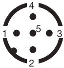
| Pin | Assignment |
|---|---|
| 1 | L+ (24 V processor) |
| 2 | P24 (24 V valve unit) |
| 3 | L- (0 V GND processor) |
| 4 | C/Q (IO-Link) |
| 5 | N24 (0 V GND valve unit) |
The housing with IP65/67 protection eliminates the need for further protective housing such as a control cabinet.
WARNING
Malfunctioning caused by electrostatic discharge. Electrostatic discharge at the device may cause malfunctioning.
All articles in the following table are equipped with integrated check valves.
| Circuit Function | QNn value air [l/min] | Switching time Opening [ms] | Switching time Closing [ms] | Article no. (D6/D8) | Article no. (D1/4" / 5/16") |
|---|---|---|---|---|---|
| C (CF C) | 270 | 15 | 15 | 357762 | 373702 |
| D (CF D) | 310 | 15 | 15 | 20002355 | on request |
| H (CF H) | 270 | 20 | 25 | 370110 | 373703 |
| L (CF L) | 290 | 20 | 25 | 382177 | on request |
| Z (CF Z) | 290 | 20 | 25 | 371372 | on request |
Explore similar products in our catalog