

PN16

BURKERT 20108915 Type 8647 AirLINE SP pneumatic valve island features 48x 3/2-way function C valves, 11 mm width, G 1/4 supply, D6 ports, P HotSwap, check valves, and Siemens ET 200SP integration.
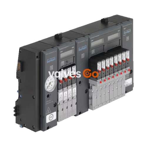
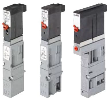
BURKERT 20108915 (Type 8647) AirLINE SP is a modular electropneumatic automation system configured as a 48-station valve block. Designed specifically for direct integration into Siemens SIMATIC ET 200SP and SIMATIC ET 200SP HA distributed I/O systems, the assembly incorporates 48 individual 3/2-way normally closed (circuit function C) flipper solenoid pilot valves (Type 6524) on an 11 mm station pitch. It mounts directly onto standard DIN rails in control cabinets, establishing electrical connections through the ET 200SP backplane bus while operating as an integrated pneumatic slave.

This specific configuration features G 1/4 primary supply ports (P) and exhaust ports (R, S), bottom-oriented D6 mm push-in working connections, 2 intermediate supply feed modules (PSU-M), integrated pneumatic HotSwap valves in channel 1 (P), and integrated non-return check valves in channels 3 (R) and 5 (S). The assembly is certified for use in potentially explosive atmospheres categorized as Zone 2 under ATEX and IECEx (Ex ec IIC T4 Gc).
| Parameter | Specification |
|---|---|
| Valve Island Type | Type 8647 AirLINE SP (Revision 2) |
| Article Number (MPN) | 20108915 |
| Total Valve Stations | 48 stations (48x single 3/2-way pilot valves) |
| Circuit Function | Circuit function C (3/2-way, servo-assisted, normally closed) |
| Station Pitch / Width per Station | 11 mm |
| Pneumatic Supply Connection 1 (P) | G 1/4 thread |
| Pneumatic Exhaust Connections 3 (R), 5 (S) | G 1/4 thread (with integrated check valves) |
| Pneumatic Working Ports 2 (A) | D6 mm push-in tube coupling (bottom module exit) |
| Operating Pressure Range | 2.5 bar to 10.0 bar (overpressure to atmospheric) |
| Nominal Air Flow Rate ($Q_{Nn}$) | Approx. 240 l/min (base 300 l/min, reduced by ~20% with P HotSwap) |
| Operating Medium | Lubricated or oil-free dry compressed air, neutral gases (ISO 8573-1:2010, Class 7.4.4, 5 µm filtration recommended) |
| Medium Temperature Range | 0 °C to +50 °C |
| Ambient Temperature Range | 0 °C to +55 °C |
| Operating Voltage | 24 V DC (±10%, SELV/PELV, max. 2.4 Vss ripple) |
| Nominal Power Consumption | 0.8 W per pilot valve (inrush 40 mA, holding 28 mA after 120 ms) |
| Nominal Operating Mode | Continuous operation (100% duty cycle) |
| Switching Times (ISO 12238) | Opening: 15 ms; Closing: 28 ms |
| Intermediate Supply Modules | 2 units (PSU-M, required after every 24 valve functions) |
| Explosion Protection Marking | II 3 G Ex ec IIC T4 Gc (BVS 18 ATEX E 078 X / IECEx BVS 18.0068 X) |
| Degree of Protection | IP20 (verified IP65 inside suitable closed control cabinet) |
| Communication Interface | Siemens SIMATIC ET 200SP / ET 200SP HA backplane bus (PROFINET IO / PROFIBUS DP) |
Type 8647 comprises modular pneumatic and electronic base sub-assemblies arranged between rigid connection units. Left (PSU-L) and right (PSU-R) connection units supply compressed air, vent exhaust, and anchor the block mechanically to the DIN rail.
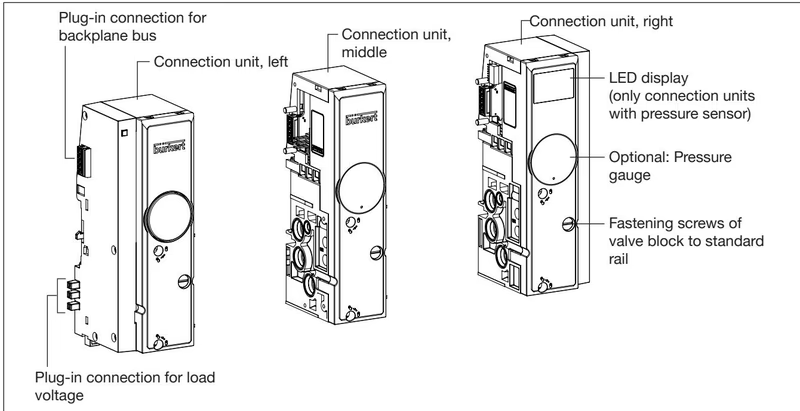
Because fluidic guidelines require an intermediate air feed after every 24 valve functions, configuration 20108915 incorporates two central intermediate feed units (PSU-M). This segmentation maintains supply volume across all 48 working stations, preventing local pressure drops during simultaneous valve actuations.
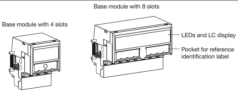
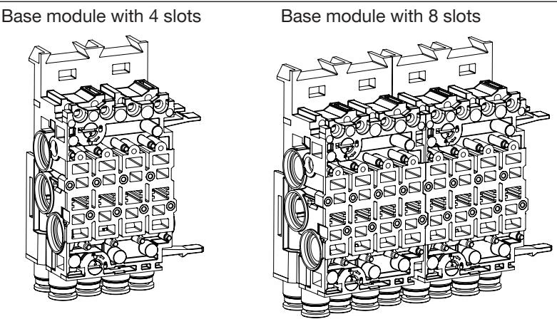
Each valve segment consists of an electronic base module (PQ module) and a matching pneumatic base module:
Configuration 20108915 is built to Revision 2 (REV.2) manufacturing standards. REV.2 includes mechanical and fluidic optimizations over earlier revisions:
Pneumatic piping must supply clean, conditioned compressed air complying with ISO 8573-1:2010 Class 7.4.4. Connections must adhere to specified torque limits:
| Connection Port | Marking | Thread / Coupling Type | Recommended Torque | Maximum Torque |
|---|---|---|---|---|
| Main Air Supply | P / 1 | G 1/4 | 4.0 to 7.0 Nm | 20.0 Nm |
| Exhaust / Deaeration | R / 3, S / 5 | G 1/4 | 4.0 to 7.0 Nm | 20.0 Nm |
| Auxiliary Pilot Air (if used) | X | M5 | 1.0 to 1.2 Nm | 3.0 Nm |
| Working Line Output | 2 (A) | D6 mm push-in | Hand insertion to internal stop | — |
Exhaust Ventilation and Backpressure Prevention
Never seal or throttle deaeration connections (3/R and 5/S) or pilot exhaust port X. Insufficient exhaust air cross-sections generate backpressure that can trigger unintended actuator movements. Always route exhaust lines via adequately sized silencers or collector manifolds.
Pneumatic tubing inserted into the D6 mm push-in connectors must comply with ISO 14743:2020 dimensions. Polyamide (PA) tubing with an outside diameter of 6 mm requires an outer tolerance of ±0.08 mm and a minimum retention force of 120 N. Cut all pneumatic tubing squarely before pushing firmly past the internal O-ring seal.
Type 8647 connects directly to the backplane bus of the Siemens SIMATIC ET 200SP or ET 200SP HA station. System engineering is supported through multiple configuration pathways:
Dedicated Power Supply Segmentation
Mount a light-colored Siemens BaseUnit (type BU...D or BU...D/T) on the standard rail immediately to the left of valve block 8647. This isolates the 24 V DC load voltage from the preceding PLC logic cards, ensuring compliance with the ±10% voltage tolerance and meeting current supply requirements.
Diagnostic messages generated by the electronic base modules include wire break, coil short circuit, load voltage loss, and switching cycle limits. The switching cycle counter monitors pilot valve cycles and actuator strokes separately via internal non-volatile memory.
Configuration 20108915 incorporates two critical safety and maintenance functions:
Operational Restrictions in Explosive Atmospheres
Pneumatic HotSwap of individual valves under line pressure must not be performed in active ATEX/IECEx Zone 2 hazardous areas. Disconnect operating pressure and de-energize the assembly before replacing valves within hazardous locations.
When implemented alongside Siemens fail-safe power modules (F-PM-E 24VDC/8A PPM ST), safety-related shut-off complies with ISO 13849-1 and IEC 62061 standards. For correct F-PM-E operation, set the maximum dark test readback time between 1.5 ms and 2.5 ms, and the switch-on test readback time to 0.8 ms.
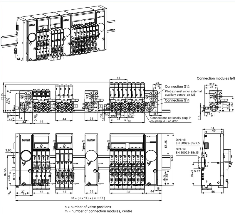
During cabinet layout, maintain a minimum clearance of 50 mm between the upper edge of the valve block and adjacent wire ducts or cabinet surfaces (80 mm if top EVS terminal plugs are used) to allow ventilation and screwdriver access to valve mounting screws.
If valve replacement is required, tighten valve fastening screws alternately in diagonal pairs to 0.15 Nm:
| Item | Description | Content | Article No. |
|---|---|---|---|
| Replacement Valve (no manual override) | Type 6524 3/2-way CF C, 2.5–10 bar, 24 V DC, REV.2 | 1 pc | 20029924 |
| Replacement Valve (with manual override) | Type 6524 3/2-way CF C, 2.5–10 bar, 24 V DC, REV.2 | 1 pc | 20029918 |
| Valve Seal Kit | Replacement seals FM24 for Type 6524 3/2-way REV.2 | 12 pcs | 20024336 |
| Module Seal Kit | Replacement module seals for Type MP16 | 4 pcs | 20024339 |
| Pneumatic Base Unit | 4-fold, 11 mm width, D6 push-in, FM20, HotSwap, RSV | 1 pc | 20040335 |
| Intermediate Feed Unit | PSU-M intermediate supply unit, 11 mm, G 1/4 | 1 pc | 20030063 |
| Left Interface Unit Kit | Interface module mechanical set for Type 8647 | 1 set | 20029826 |
| Blanking Cover Plate | Cover plate for unused valve slots (REV.2) | 1 pc | 661092 |
| Push-in Connector | Spare D6 mm push-in cartridge, brass nickel-plated | 8 pcs | 20024340 |
Explore similar products in our catalog


