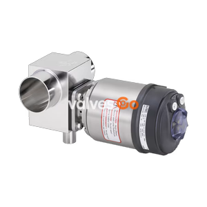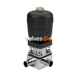
Type 2032

BURKERT 20109570 (Type 2933) is a 2/2-way manual diaphragm valve with G 1/2" stainless steel pipe body (316L/1.4435 BN2), high-temp EPDM diaphragm, optical position indicator, and 0-10 bar operating pressure.
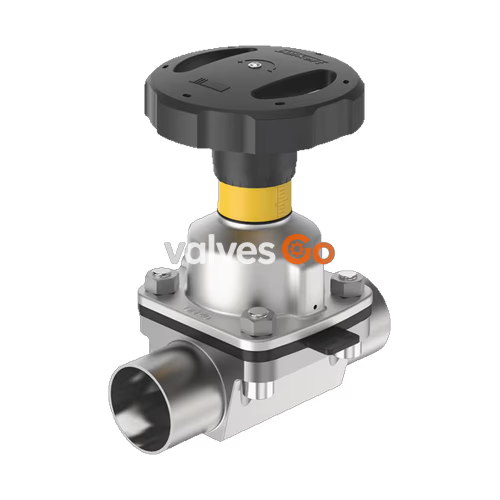
BURKERT 20109570 (Type 2933) is a 2/2-way manually operated diaphragm valve designed for shut-off control in sanitary, sterile, and processing applications. The valve incorporates a stainless steel tube valve body (VP) made of 1.4435-BN2/UNS S31603 (316L) with G 1/2" internal threaded ports, an autoclavable stainless steel diaphragm bonnet, and a high-temperature EPDM diaphragm (material code AD). The internal flow path delivers a water flow coefficient Kv of 7.0 m³/h (Cv of 8.2 gal/min) with minimal dead space, supporting operating pressures from 0 to 10 bar across temperatures from -10 °C to +143 °C.
The manual actuator features a compact 45 mm diameter handwheel (size S), an integrated optical position indicator with graduated scale, and an adjustable single minimum stroke limiter (closing limiter). The valve is certified for clean-in-place (CIP) and steam-in-place (SIP) processes and complies with FDA 21 CFR, USP Class VI, and European Regulation (EC) 1935/2004 requirements for food, beverage, and pharmaceutical contact.
| Parameter | Specification |
|---|---|
| Article number | 20109570 |
| Valve Type | Type 2933 (Basic manual actuator) |
| Valve function | 2/2-way shut-off valve |
| Port connection | G 1/2" internal thread (parallel pipe thread) |
| Product key connection code | GM84 |
| Diaphragm size | 15 |
| Nominal diameter | DN 15 (1/2") |
| Body construction | Tube valve body (VP) |
| Body material | Stainless steel pipe 1.4435-BN2 / UNS S31603 (316L) |
| Diaphragm bonnet material | Stainless steel 1.4308 |
| Handwheel material | Stainless steel (Size S, Ø 45 mm) |
| Valve spindle material | Stainless steel 1.4305 |
| Diaphragm material | EPDM high-temperature (AD) |
| Operating medium pressure | 0 to 10 bar (static) |
| Medium temperature range | -10 °C to +143 °C (steam sterilisation: +150 °C for 60 min) |
| Ambient temperature range | -10 °C to +130 °C (short-term up to +150 °C, autoclavable) |
| Flow coefficient Kv (water) | 7.0 m³/h (Cv = 8.2 gal/min) |
| Position indicator | Optical indicator with rotation and stroke scale |
| Stroke limitation | Adjustable minimum stroke limiter (closing limiter) |
| Product identification | Data matrix code on type label |
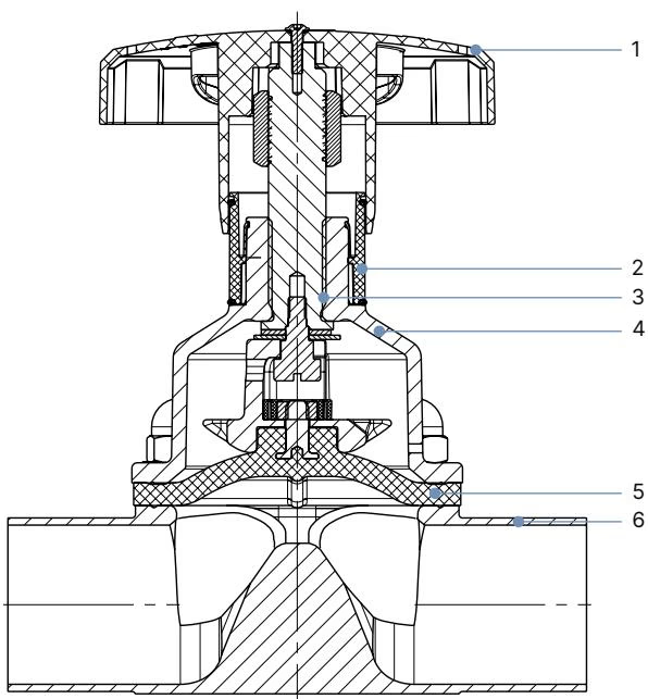
| Item No. | Element | Material |
|---|---|---|
| 1 | Handwheel | Stainless steel (optionally polyphenylene sulphide PPS) |
| 2 | Visual position indicator | Polyamide (PA) / Stainless steel 1.4305 |
| 3 | Valve spindle | Stainless steel 1.4305 |
| 4 | Diaphragm bonnet | Stainless steel 1.4308 (optionally PPS) |
| 5 | Diaphragm | High-temperature EPDM (AD), bayonet catch attachment |
| 6 | Valve body | Stainless steel tube 1.4435-BN2 / 316L (VP) |
The EPDM (AD) elastomer diaphragm withstands steam sterilisation up to +150 °C for 60 minutes. Extending sterilisation intervals is permissible, though service intervals must be adjusted accordingly.
| Standard / Conformity | Scope and Details |
|---|---|
| EC Regulation 1935/2004 | Materials suitable for food and beverage contact according to European declaration. |
| FDA 21 CFR | EPDM compound formulation complies with US Food and Drug Administration requirements. |
| USP Class VI | In-vivo biological reactivity testing passed according to USP Class VI standards. |
| CE Conformity | Complies with applicable European Union directives and harmonised standards. |
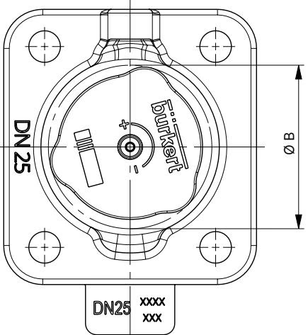
| Diaphragm Size | Handwheel Designation | Handwheel Diameter Ø B [mm] | Open Height H1 [mm] | Closed Height H2 [mm] | Pitch per Rotation [mm] |
|---|---|---|---|---|---|
| 6 | T (Tiny) | 35 | 49 | 42 | 1.5 |
| 8 | T (Tiny) | 35 | 54 | 49 | 1.5 |
| 15 | S (Small) | 45 | 84 | 78 | 1.75 |
| 20 | S (Small) | 45 | 95 | 86 | 1.75 |
| 25 | S (Small) | 45 | 101 | 90 | 1.75 |
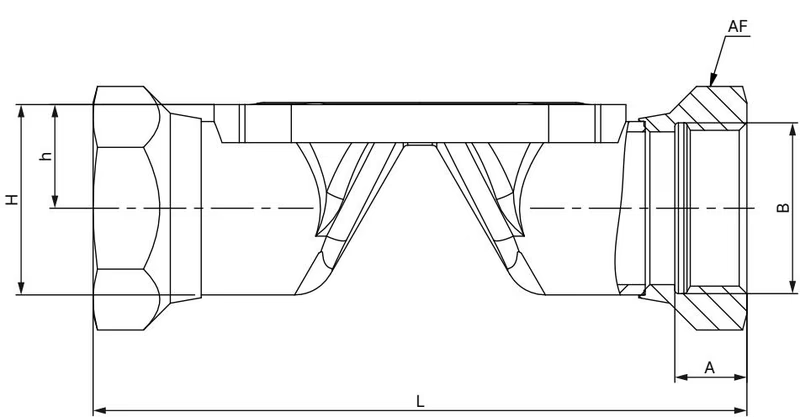
| Diaphragm Size | Port Thread B | L [mm] | A [mm] | h [mm] | H [mm] | Width Across Flats SW [mm] | Product Key |
|---|---|---|---|---|---|---|---|
| 8 | G 1/4 | 85 | 9 | 11.70 | 20.3 | 17 | GM82 |
| 15 | G 1/2 | 102 | 14 | 14.35 | 25.0 | 27 | GM84 |
| 20 | G 3/4 | 118 | 12 | 17.15 | 30.45 | 32 | GM85 |
| 25 | G 1 | 127 | 14 | 20.55 | 37.4 | 41 | GM86 |
| 32 | G 1 1/4 | 146 | 16 | 25.10 | 46.3 | 50 | GM87 |
| 40 | G 1 1/2 | 159 | 18 | 29.35 | 53.5 | 60 | GM88 |
| 50 | G 2 | 191 | 20 | 35.35 | 65.5 | 70 | GM89 |
Turning the handwheel counterclockwise lifts the spindle and opens the valve flow path. Turning the handwheel clockwise closes the diaphragm down against the weir of the tube valve body. The optical position indicator exposes a yellow mark with graduated stroke scale as the handwheel opens (30 rotation divisions on Type 2933 size S).
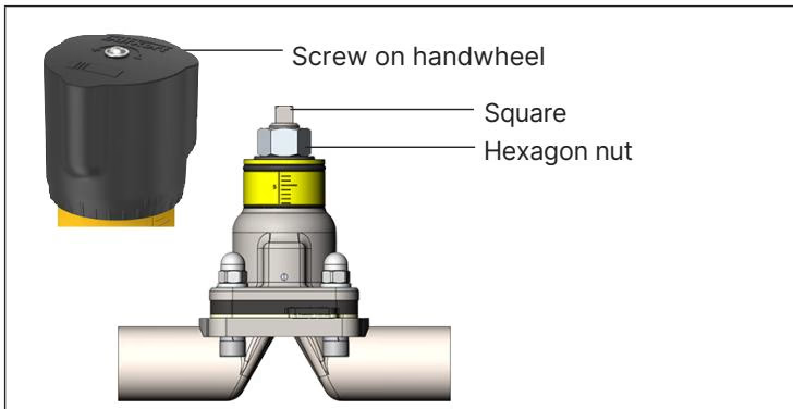
The minimum stroke limit functions as a mechanical closing limiter to protect the EPDM diaphragm from over-compression:
Operating Precaution
Never screw the hexagon nut onto the drive square of the spindle. The minimum stroke limit may only be set within the 0% to 25% opening stroke range. Tighten the handwheel only until media shut-off is achieved; excessive torque accelerates diaphragm wear.
Tightness criteria are defined as follows:
| Diaphragm Size | Static Tightness (EPDM/FKM) [Nm] | Static Tightness (PTFE) [Nm] | Dynamic Tightness (EPDM/FKM) [Nm] | Dynamic Tightness (PTFE) [Nm] |
|---|---|---|---|---|
| 8 | 0.6 | 1.1 | 0.9 | 1.2 |
| 15 | 0.8 | 1.7 | 1.5 | 2.5 |
| 20 | 0.9 | 3.0 | 2.0 | 4.5 |
| 25 | 1.2 | 3.5 | 3.6 | 5.0 |
| 32 | 2.5 | 4.0 | 8.0 | 15.0 |
| 40 | 4.5 | 7.0 | 12.0 | 15.0 |
| 50 | 6.0 | 11.0 | 15.0 | 20.0 |
A tolerance of +10% applies to all specified tightening torques.
| Diaphragm Size | Cast / Forged Body (VS, VG) EPDM [Nm] | Cast / Forged Body (VS, VG) PTFE [Nm] | Tube Valve Body (VP) EPDM [Nm] | Tube Valve Body (VP) PTFE [Nm] |
|---|---|---|---|---|
| 8 | 2.0 | 2.5 | 2.0 | 2.5 |
| 15 | 3.5 | 4.0 | 3.5 | 4.0 |
| 20 | 4.0 | 4.5 | 4.0 | 4.5 |
| 25 | 5.0 | 6.0 | 7.0 | 8.0 |
| 32 | 6.0 | 8.0 | 8.0 | 10.0 |
| 40 | 8.0 | 10.0 | 12.0 | 15.0 |
| 50 | 12.0 | 15.0 | 15.0 | 20.0 |
Installation position is arbitrary, with actuator facing upward preferred. To ensure self-draining in sanitary installations:
Pre-Installation Check
Depressurise and flush pipeline systems prior to installation. Flush out welding residue, metal shavings, and packing particulate before installing the diaphragm valve.
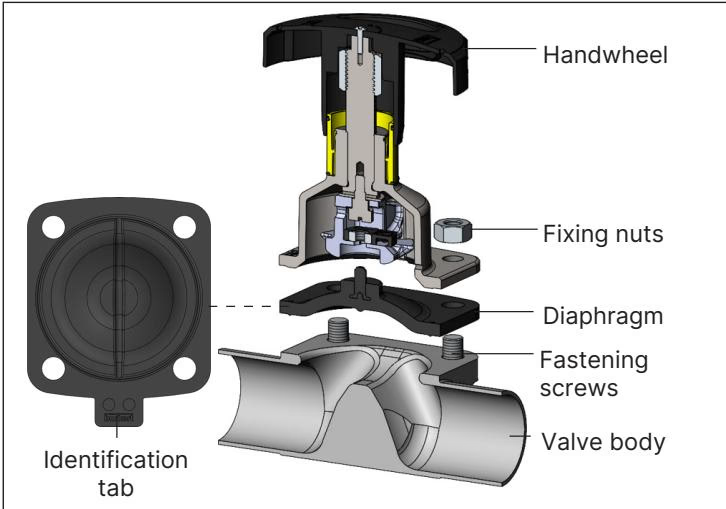
The manual actuator requires no lubrication during normal operation. Inspect the leak detection relief bore periodically. If liquid escapes, replace the diaphragm immediately.
| Diaphragm Material | Bürkert Material Code | Article Number | Fastening Mechanism |
|---|---|---|---|
| EPDM (AD) | EPDM E04 | 693 163 | Bayonet catch |
| FKM (FF) | FKM F01 | 693 164 | Bayonet catch |
| PTFE / EPDM (EA) | EPDM E04 / PTFE P05 | 20093069 | Bayonet catch |
| Advanced PTFE / EPDM (EU) | EPDM E04 / PTFE P06 | 20093079 | Bayonet catch |
| GYLON® / EPDM laminate (ER) | PTFE L08 | 693 176 | Bayonet catch |
| Accessory Description | Article Number |
|---|---|
| 4-fold nylon locking mechanism with 3 mm bracket | 93719475 |
| Inductive proximity switch (initiator) M5 | 550412 |
| Inductive proximity switch (initiator) M5 ATEX | 904779 |
Explore similar products in our catalog