Type 2032

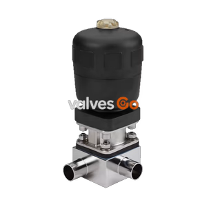
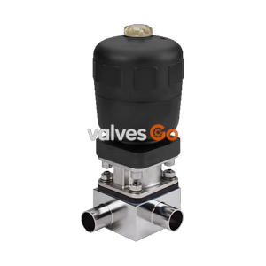
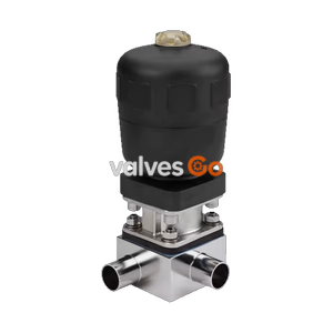
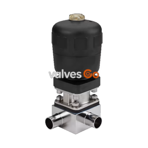
BURKERT Type 2935 manual tank bottom diaphragm valve (SKU 20112076). Features a flow-optimized stainless steel body, EPDM diaphragm, and ATEX/FDA approvals.
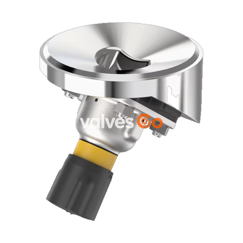
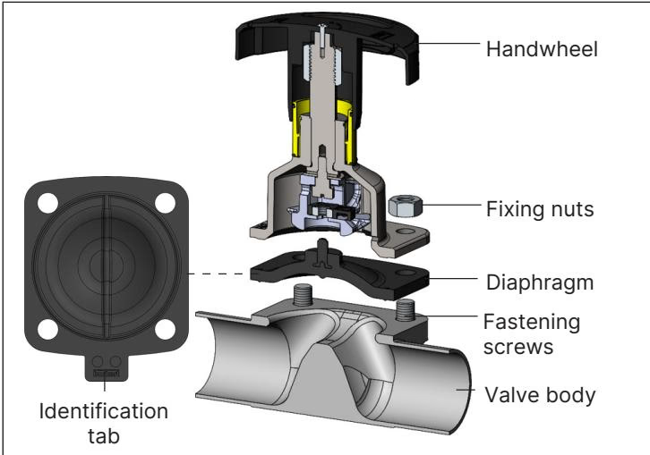
BURKERT Type 2935 manually operated diaphragm valve consists of a manually operated actuator, a diaphragm, and a tank bottom valve body. The manual actuator with a plastic or stainless steel handwheel is available with a diaphragm bonnet made of stainless steel or plastic, ensuring use in hygienic or aggressive ambient conditions. The flow-optimized valve body with minimum dead space enables high flow values and a wide range of possible applications. The actuator has a compact, autoclavable design and is compatible with all other Bürkert diaphragm valves. The manual actuator is equipped with an integrated visual position indicator, a reproducible stroke scale, and an adjustable closing limiter.
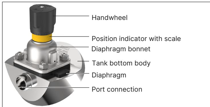
The Type 2935 diaphragm valve meets stringent industry standards for hygienic and potentially explosive environments.
| Conformity / Approval | Description |
|---|---|
| ATEX / IECEx | Category 2 device suitable for zone 1/21 and zone 2/22. Ex h IIC T4...T2 Gb / Ex h IIIC T135 °C...T300 °C Db. |
| 3-A Sanitary Standards | Products comply with 3-A Sanitary Standards Inc (3-A SSI). |
| FDA | Diaphragms made of EPDM, PTFE/EPDM, advanced PTFE/EPDM, and GYLON®/EPDM comply with the Code of Federal Regulations published by the FDA. |
| USP Class VI | Diaphragms are tested according to United States Pharmacopeial Convention (USP) Class VI. |
| EC 1935/2004 | Diaphragms are suitable for use with food and beverages according to EC Regulation 1935/2004/EC. |
| TA Luft | Technical instruction on air quality control. |
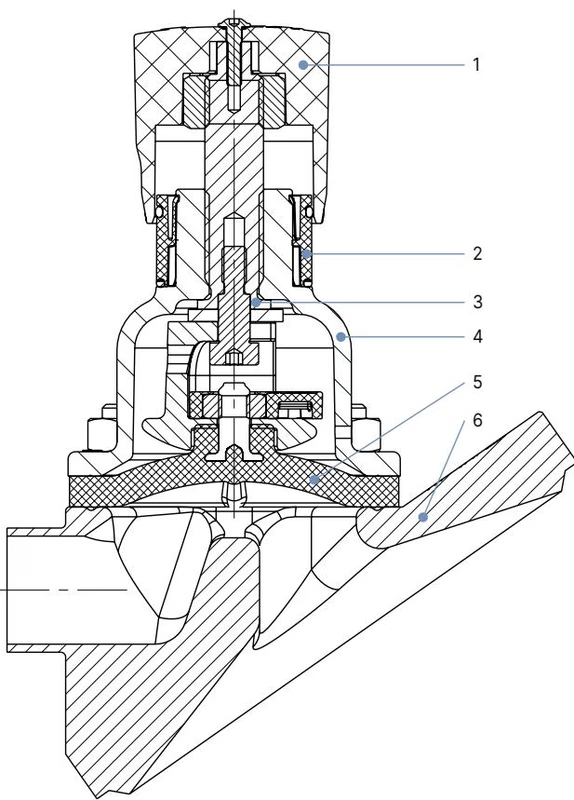
| No. | Element | Material |
|---|---|---|
| 1 | Handwheel | Polyphenylene sulphide (PPS), stainless steel 1.4308 |
| 2 | Visual position indicator | Polyamide (PA), stainless steel 1.4305 |
| 3 | Valve spindle | Stainless steel 1.4305 |
| 4 | Diaphragm bonnet | Stainless steel 1.4308, polyphenylene sulphide (PPS) |
| 5 | Diaphragm | EPDM (AD), PTFE/EPDM (EA), advanced PTFE/EPDM (EU), laminate of GYLON® and EPDM (ER) |
| 6 | Valve body | Stainless steel block material 1.4435 according to DIN EN 10088 and 316L according to ASTM A479 / A479M |
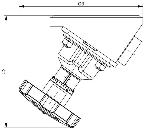
Note: Dimensions in mm, unless otherwise stated.
| Diaphragm size | C2 | C3 |
|---|---|---|
| 8 | 69 | 71 |
| 15 | 103 | 101 |
| 20 | 116 | 115 |
| 25 | 127 | 129 |
| 40 | 182 | 201 |
| 50 | 203 | 217 |
| 65 | 265 | 305 |
| 80 | 336 | 278 |
| 100 | 300 | 370 |
WARNING
Risk of injury due to high pressure and escaping medium. Switch off the pressure before working on the device or system. Vent or empty the lines.
TIP
For information on containers and instructions for welding, refer to the ASME VIII Division I standard. Check the batch number indicated on the manufacturer’s certificate 3.1 supplied before starting welding work.
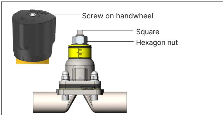
A minimum stroke limit can be set for Type 2935. This setting also serves as a closing limiter to protect the diaphragm. A hexagon nut is used to do this.
Explore similar products in our catalog