Type 2032

BURKERT 20112730 Type 2933 2/2-way manual diaphragm valve. Features DN 25 welded connection, forged stainless steel body, PTFE/EPDM diaphragm, and handles up to 10 bar. CIP/SIP capable.
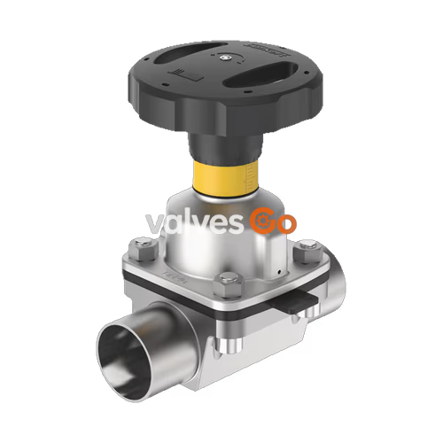
The BURKERT Type 2933 (Article No. 20112730) is a 2/2-way diaphragm valve with a manually operated actuator. The manual actuator with a PPS (Polyphenylene sulphide) handwheel ensures reliable use in hygienic or aggressive ambient conditions. The flow-optimised forged stainless steel valve body with minimum dead space enables high flow values and a wide range of possible applications. The actuator has a compact, autoclavable design and is equipped with an integrated visual position indicator with a scale, a reproducible stroke scale, and a single min-stroke limiter (closing limiter).
This specific model features a DN 25 welded connection, a forged stainless steel 316L body, and a PTFE diaphragm with an EPDM backing membrane. It is designed to handle medium pressures up to 10 bar and temperatures ranging from -10 °C to +130 °C, making it fully CIP and SIP capable for demanding process environments.
| Feature | Specification |
|---|---|
| Port connection | DN 25 (NPS 1) - 29.0x1.5 Welded (DIN 11850 R2 / DIN 11866 Series A / DIN EN 10357 Series A) |
| Valve body material | Forged stainless steel 316L/1.4435 BN2 |
| Diaphragm material | PTFE with EPDM backing membrane |
| Nominal pressure | 0 - 10 bar (PN 10 / Class 150) |
| Medium temperature | -10 °C to +130 °C |
| Ambient temperature | -10 °C to +130 °C (short-term up to +150 °C), autoclavable |
| Kv value (water) | 17 m³/h (Cv value: 19.8 gal/min) |
| Actuator material | PPS handwheel, optical position indicator with scale (45 mm diameter) |
ATEX Safety Note
When operating in potentially explosive atmospheres, ensure proper grounding of the valve body and actuator to prevent electrostatic charging hazards. Only use cleaning agents certified for explosive environments.
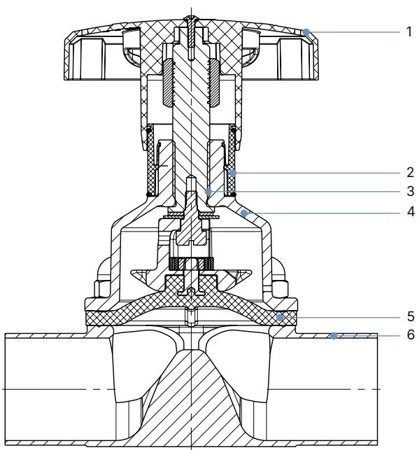
| No. | Element | Material |
|---|---|---|
| 1 | Handwheel | Polyphenylene sulphide (PPS), stainless steel 1.4308 |
| 2 | Visual position indicator | Polyamide (PA), Stainless steel 1.4305 |
| 3 | Valve spindle | Stainless steel 1.4305 |
| 4 | Diaphragm bonnet | Stainless steel 1.4308, polyphenylene sulphide (PPS) |
| 5 | Diaphragm | PTFE with EPDM backing membrane |
| 6 | Valve body | Forged stainless steel 316L/1.4435 BN2 |
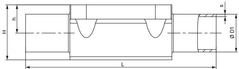
Dimensions for DN 25 (DIN 11850-2 / DIN 11866 Series A / DIN EN 10357 Series A):
| Diaphragm size | Port connection DN | ∅D1 | s | L | h | H | Product key |
|---|---|---|---|---|---|---|---|
| 25 | 25 | 29.0 | 1.5 | 129 | 19.0 | 37.0 | SD44 |
(Note: Dimensions in mm, unless otherwise stated)
Installation Position & Self-Draining
The installation position is generally any, but preferably with the actuator facing up. To ensure self-draining, the self-draining angle (α) depends on the valve body size and the inner diameter of the port connection (DN). The marking on the port connection of the valve body serves as an orientation aid and must point upwards. The actual self-draining angle must be set with a suitable measuring tool.
Welding Instructions: To prevent damage, the actuator and diaphragm must be dismantled before welding the valve body into the pipeline. After welding, smooth the body surface if necessary and clean the valve body thoroughly before reassembling the diaphragm and actuator. Tighten the fastening screws crosswise in 3 stages to ensure the diaphragm is positioned and pressed evenly.
Explore similar products in our catalog