

PN16

BURKERT 20112850 Type 8640 is an 11 mm REV3 pneumatic valve island with mixed 3/2-way valves, G 1/4 supply ports, D6 bottom working ports, integrated P HotSwap, exhaust check valves, and IP20 single-wire control.
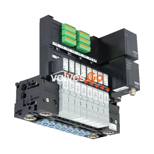
BURKERT 20112850 Type 8640 is a modular pneumatic valve island designed for compact automation assemblies, built on an 11 mm station-width platform in hardware Revision 3 (REV3). The unit is factory-configured with a mixed valve population of 3/2-way functions, G 1/4 pneumatic supply ports, and bottom-facing push-in D6 working ports. Electrical actuation is managed via discrete single wiring without internal fieldbus hardware, providing straightforward integration into conventional I/O control systems.
Hardware article 20112850 incorporates a pneumatic HotSwap shut-off valve on supply port 1 (P) and integrated non-return check valves (RSV) inside exhaust channels 3 (R) and 5 (S). These mechanical features allow individual pilot valves to be replaced during live plant operation while preventing pressure surges or cross-exhaust interference among neighboring valve slices. The valve terminal mounts directly to standard EN 50022 DIN rails and carries an IP20 ingress protection rating.
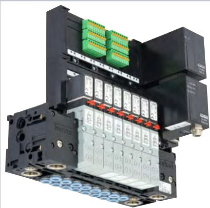
| Parameter | Specification (Article 20112850) |
|---|---|
| Valve Island Type | Type 8640 |
| Hardware Generation | Revision 3 (REV3) |
| Station Width | 11 mm |
| Valve Population | Mixed valve population (3/2-way functionality) |
| Operating Pressure Range | 2.5 bar to 10.0 bar (overpressure to atmospheric pressure) |
| Flow Rate ($Q_{Nn}$) | 200 l/min to 300 l/min (flow reduced by approx. 20% with HotSwap P shut-off) |
| Operating Medium | Compressed dry air (lubricated or unlubricated), neutral gases |
| Air Quality Standard | ISO 8573-1:2010, Class 7.4.4 (5 µm filtration recommended) |
| Medium Temperature | 0 °C to +50 °C |
| Ambient Temperature | 0 °C to +55 °C |
| Storage Temperature | -20 °C to +60 °C |
| Operating Voltage | 24 V DC (±10% voltage tolerance, max. 1 Vss residual ripple) |
| Power Consumption per Valve | 0.8 W (single 3/2-way valve) / 2 x 0.8 W (double valve with power reduction) |
| Operating Mode | Continuous operation (100% duty cycle) |
| Protection Class | III according to VDE 0580 |
| Ingress Protection | IP20 (IP65 inside closed control cabinet) |
| Supply Port 1 (P), Exhaust 3 (R), 5 (S) | G 1/4 |
| Working Ports 2 (A), 4 (B) | Push-in connector D6 (Ø 6 mm, bottom position) |
| Valve Body Material | Polyamide (PA) |
| Seal Materials | FKM, NBR, and PUR |
| Mounting Type | DIN-rail installation (EN 50022 35 x 7.5 or 35 x 15) |
Revision 3 of the Type 8640 11 mm valve island introduces standardized valve interfaces and improved pneumatic efficiency over earlier hardware revisions:
Integrated HotSwap and Check Valve Protection
The P-shut-off mechanism on supply duct 1 (P) isolates pressure from the selected station during servicing, enabling hot swapping of solenoid valves without depressurizing the entire pneumatic manifold. Integrated check valves in ducts 3 (R) and 5 (S) prevent backpressure pulses from triggering inadvertent actuator motion.
The pneumatic manifold is composed of modular polyamide blocks locked together with built-in snap connectors. Working lines exit through the bottom face of the base modules, maintaining a compact cabinet footprint.
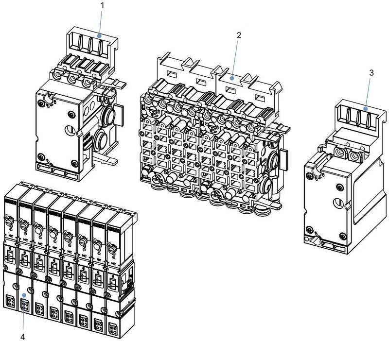
| Element No. | Assembly Component | Functional Description |
|---|---|---|
| 1 | Pneumatic connection module, left | Houses primary supply and exhaust thread connections (G 1/4) |
| 2 | Basic pneumatic modules | 4-fold blocks accommodating D6 push-in ports, HotSwap seats, and RSV valves |
| 3 | Pneumatic connection module, right | Closes pneumatic manifold channels or provides secondary supply feeds |
| 4 | Pilot solenoid valves | Type 6524 3/2-way rocker/flipper valves secured by two M2 screws |
BURKERT 20112850 is engineered for standard DIN-rail mounting inside electrical enclosures or decentralized pneumatic control cabinets.
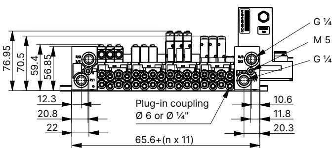
Push-in connections comply with ISO 14743:2020. Strict adherence to tubing dimensions and insertion procedures ensures leak-free operation up to the rated 10 bar limit.
| Tubing Material | Outside Diameter (OD) | Permissible OD Deviation | Minimum Tensile Holding Force |
|---|---|---|---|
| Polyamide (PA) | 6 mm | ±0.08 mm | 120 N |
| Polyurethane (PU) | 6 mm | ±0.10 mm | 100 N |
Tubing Installation Practice
Article 20112850 operates with parallel discrete wiring rather than an integrated serial fieldbus module. Each pilot solenoid connects directly via individual stranded conductors, making it suitable for direct interface with PLC digital output modules.
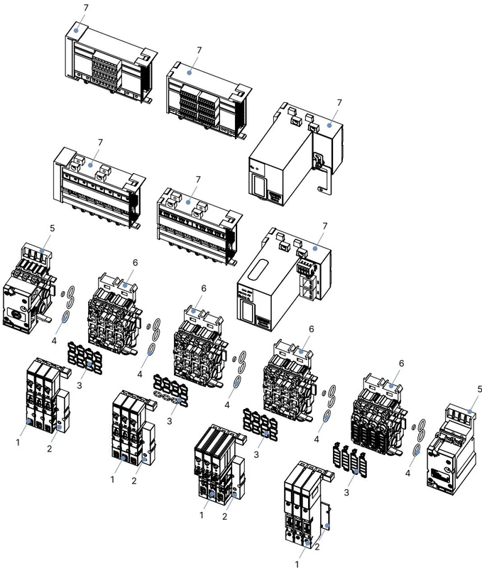
| Item | Description | Packaging Content | Article No. |
|---|---|---|---|
| 1 | Type 6524 3/2-way NC valve, DN 4.0, 2.5-10 bar, 24 V DC (REV3, FM20) | 1 piece | 20029918 |
| 1 | Type 6524 3/2-way NO valve, DN 4.0, 2.5-10 bar, 24 V DC (REV3, FM20) | 1 piece | 20029919 |
| 1 | Type 6524 2 x 3/2-way NC valve, DN 4.0, 2.5-10 bar, 24 V DC | 1 piece | 186260 |
| 2 | Cover plate for unused valve slot (Type 6524/6525 REV2/REV3) | 1 piece | 661092 |
| 3 | Spare valve seals FM20 (for Type 6524 double valve) | 12 pieces | 20016305 |
| 3 | Spare valve seals FM24 (for Type 6524 single valve) | 12 pieces | 20024336 |
| 4 | Spare module seals for Type MP16 basic pneumatic module | 4 pieces | 20024339 |
| 5 | Supply unit right, Type 8640, 11 mm, G 1/4 | 1 piece | 20040351 |
| 5 | Supply unit left, Type 8640, 11 mm, G 1/4 | 1 piece | 20040352 |
| 6 | Pneumatic base unit 4-fold, 11 mm, D6, FM20 flange, HotSwap, RSV | 1 piece | 20040335 |
| - | Cover for unused electrical connection slot | 1 piece | 653670 |
| Fault Observed | Probable Cause | Remedial Action |
|---|---|---|
| Solenoid valves fail to switch | Missing or insufficient 24 V DC supply voltage | Check power wiring and verify voltage at terminal matches 24 V DC ±10% |
| Manual override locked in engaged position | Rotate manual override 90° counter-clockwise to zero position | |
| Operating air pressure below 2.5 bar | Verify main supply delivers between 2.5 bar and 10 bar at port 1 (P) | |
| Delayed valve actuation or continuous exhaust blow-off | Upstream air volume restricted by undersized supply lines | Increase supply line diameter and verify pressure drop during multi-valve cycling |
| Block pressurized while valves are in energized state | De-energize all coils prior to applying primary pneumatic pressure | |
| Silencer on exhaust duct 3/5 clogged | Clean silencer element or replace with high-flow exhaust silencer | |
| Manifold block leakage between slices | Damaged, pinched, or missing O-rings between basic modules | Disassemble sub-modules, inspect MP16 profile seals, and replace damaged O-rings |
Explore similar products in our catalog


