

PN16

BURKERT 20112962 Type 8640 is an AirLINE Quick modular pneumatic valve island block with 4x 3/2-way function C valves, 11 mm station width, G 1/4 supply port, and D6 bottom working ports for 2.5 to 10 bar.
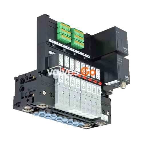
BURKERT 20112962 Type 8640 is an AirLINE Quick modular pneumatic valve island block configured with four 3/2-way type C (normally closed) valves on an 11 mm station width grid. Engineered for direct control of process actuators and pneumatic machinery, this assembly integrates an aluminium AirLINE Quick base adapter featuring brass G 1/4 main air supply connections and brass push-in D6 working ports exiting through the bottom plate.
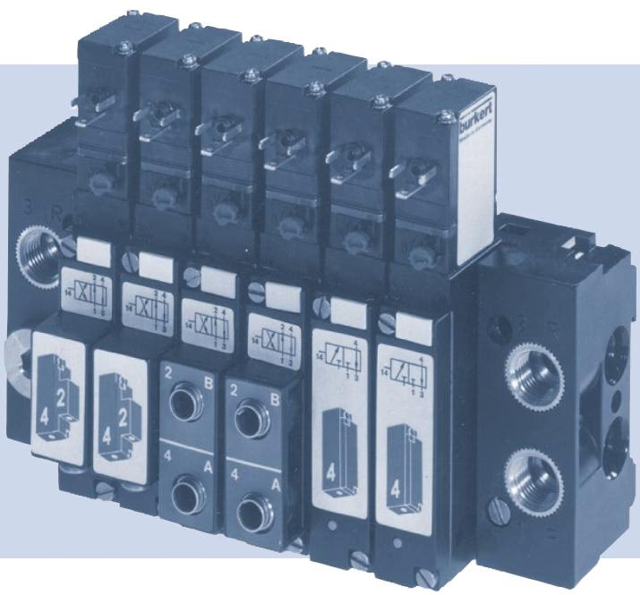
The unit operates at a nominal pressure range of 2.5 to 10 bar within an operating medium temperature window of 0 °C to +50 °C and an ambient temperature range of 0 °C to +55 °C. Configured as a revision 3 design with single electrical wiring, the assembly delivers an IP20 ingress protection rating in industrial control enclosures.
The manifold assembly houses compact solenoid-actuated directional control valves mounted on dedicated base segments. Each valve contains a pilot valve Type 6106 operating a main spool mechanism with NBR seat seals.
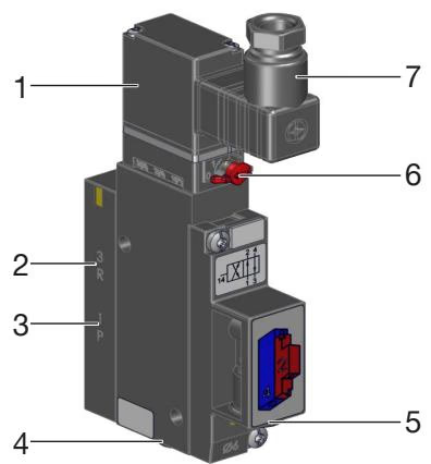
| Connection Number | Port Identification | Function |
|---|---|---|
| 1 | P | Central pressure feed port (G 1/4) |
| 2 | A / OUT | Working outlet port (D6 push-in) |
| 3 | R | Exhaust vent port |
| 4 | B / OUT | Secondary working outlet port (when 4/2 configuration is used) |
For circuit function C (3/2-way normally closed), pressure port 1 (P/NC) remains shut in the de-energised rest position, while working port 2 (A/OUT) communicates directly with exhaust port 3 (R/NO). Energising the pilot coil opens port 1 to port 2 while closing exhaust port 3.
Each valve station incorporates an integrated mechanical manual override allowing manual actuation during setup or maintenance routines without electrical power.
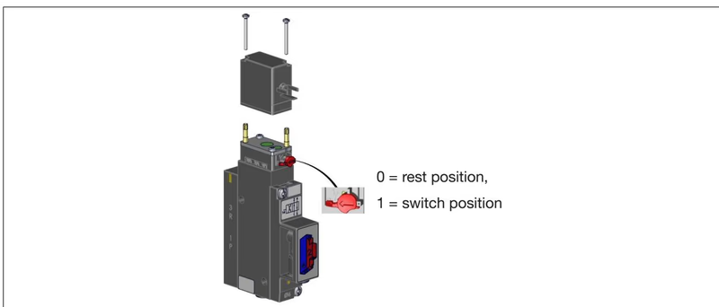
To lock the manual override into active position, press the override element inward and turn it 90° clockwise until it hits the mechanical stop. In this position, the override remains mechanically latched and will not reset automatically. Before resuming automated electrical control, turn the manual override counter-clockwise back to the 0 position.
Operating Precaution
Only operate manual overrides when the electrical control supply is turned off. For standard electrical operation, verify that every manual override is in its unlatched zero position.
| Technical Attribute | Specification Value |
|---|---|
| Product Type / Generation | Type 8640 / Revision 3 |
| Order Code (Article Number) | 20112962 |
| Valve Configuration | 4x 3/2-way valve function C (NC) |
| Station Grid Width | 11 mm |
| Supply Port 1 (P) | G 1/4 female thread (AirLINE Quick brass fitting) |
| Working Ports 2 (A) | D6 push-in connectors (brass, bottom exit) |
| Operating Pressure Range | 2.5 bar to 10.0 bar |
| Minimum Pressure Differential (Port 1 to Port 3) | 2.0 bar |
| Fluid Temperature Range | 0 °C to +50 °C |
| Ambient Operating Temperature | 0 °C to +55 °C |
| Storage Temperature Limits | -40 °C to +55 °C |
| Medium Compatibility | Filtered compressed air (particle size ≤ 10 µm) or neutral gases (≤ 5 µm) |
| Seal Material | Nitrile butadiene rubber (NBR) |
| Mechanical Installation Type | AirLINE Quick aluminium interface plate |
| Internal Communication / Variant | Without internal bus (single-wire architecture) |
| Ingress Protection Rating | IP20 |
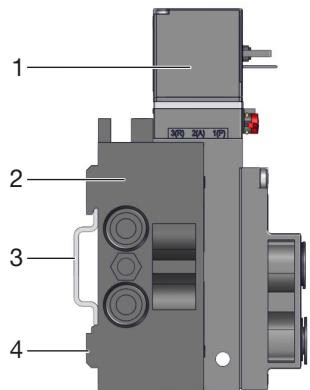
Type 8640 blocks support standard DIN-rail mounting or direct surface mounting. The integrated clamping mechanism secures the block assembly onto standard profiles complying with EN 50022 (35 x 15 mm or 35 x 7.5 mm).
| Connection / Assembly Point | Thread Size | Recommended Torque [Nm] | Maximum Torque [Nm] |
|---|---|---|---|
| Main Supply / Exhaust (P, R/S) | G 1/4 | 4.0 to 7.0 Nm | 20.0 Nm |
| Auxiliary / Valve Ports | G 1/8 | 3.0 to 6.0 Nm | 7.0 Nm |
| Valve to Base Module Fastening | Screw M2.5 / M3 | 0.6 ±0.1 Nm | — |
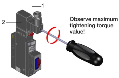
| Pilot Solenoid Coil Screw (Step 1) | Screw M2 | 0.1 ±0.05 Nm | — |
| Pilot Solenoid Coil Screw (Step 2) | Screw M2 | 0.2 ±0.05 Nm | — |
If installation clearance requires an alternate cable routing, the pilot solenoid can be rotated 180° by loosening the M2 fastener, turning the coil body, and tightening it down in two successive increments of 0.1 Nm and 0.2 Nm.
Connection lines must be pushed straight into the D6 push-in fittings until they reach the internal mechanical stop. Tubing must satisfy a minimum material hardness of 40 Shore D in compliance with DIN 53505 or ISO 868, with outer diameter tolerances according to DIN 73378 (permissible deviation ±0.1 mm from nominal size).
Tubing Preparation
Cut hose ends cleanly at a strict 90° right angle without burrs. Diagonal cuts or longitudinal scratches along the outer tubing circumference reduce claw retention and compromise seal integrity under pressure.
| Hose Outer Diameter (OD) | 3 mm | 4 mm (5/32") | 6 mm (1/4") | 8 mm (5/16") | 10 mm (3/8") | 12 mm (1/2") | 14 mm | 16 mm (5/8") |
|---|---|---|---|---|---|---|---|---|
| Polyamide (PA) Tubing | 60 N | 70 N | 120 N | 170 N | 250 N | 300 N | 300 N | 350 N |
| Polyurethane (PU) Tubing | 25 N | 50 N | 100 N | 150 N | 200 N | 200 N | 250 N | 300 N |
For flexible polyurethane (PU) tubing lines, installing internal support sleeves (part ID 20099400) provides extra mechanical stability and seal reliability inside the push-in gripping collets.
Model 20112962 uses single-wired terminal terminations. Individual pilot coils accept standard DIN EN 175301-803 Form C connectors, such as Type 2516 cable plugs.
| Protective Conductor Parameter | Verification Value |
|---|---|
| Maximum Resistance | ≤ 0.1 Ω |
| Test Voltage | 12 V |
| Test Current | 1 A |
Continuous Operation Guideline
When valve islands remain in standby or non-energised states for extended periods, execute at least 1 to 2 switching cycles per day to maintain lubricant distribution across internal NBR seals and maintain spool responsiveness.
| Malfunction Symptom | Potential Root Cause | Corrective Action |
|---|---|---|
| Valves fail to switch | Absence of electrical operating voltage or supply voltage below tolerance | Check terminal connections; confirm supply matches voltage data on coil label. |
| Manual override locked in active position | Return manual override detent to zero position. | |
| Operating feed pressure absent or below 2 bar | Verify primary air source; ensure pilot pressure exceeds 2.0 bar minimum differential. | |
| Delayed valve response or continuous exhaust blow-off | Upstream line cross-section too small causing dynamic pressure drop | Expand supply lines or install local air accumulation reservoir. |
| Block pressurised while valves were in energised state | De-energise all valve stations before charging main manifold pressure. | |
| Exhaust silencer blocked or undersized causing backpressure | Clean dirty silencer elements or replace with larger exhaust mufflers. | |
| Particle contamination inside pilot or main seat | Purge exhaust ports with pulsed compressed air or renew contaminated valve module. | |
| Pneumatic leakage at manifold interfaces | Damaged, pinched, or missing O-rings between sub-base elements | Disassemble modules, inspect elastomer seals, lubricate, and replace damaged O-rings. |
| Misaligned flat gasket between valve body and AirLINE adapter plate | Reseat gasket squarely and torque fixing screws to 0.6 ±0.1 Nm. |
Explore similar products in our catalog


