

PN16

BURKERT 20114261 (Type 8652 AirLINE) is a 24-slot valve island with PROFIBUS DPV1, aluminium AirLINE Quick base, brass D10/D6 ports, 24x 2x3/2-way CF-D valves, integrated check valves, and pneumatic HotSwap.
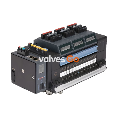
BURKERT 20114261 (Type 8652 AirLINE) is a modular 24-slot pneumatic valve island configured with a PROFIBUS DPV1 communication interface, an anodised aluminium AirLINE Quick adapter plate, and 24 double 3/2-way normally open (Circuit Function D) solenoid valve slices. Designed specifically for control cabinet integration in process automation, the system operates across a nominal working pressure range of -1 bar to 10 bar with pilot air pressure between 3 bar and 10 bar, accommodating medium and ambient operating temperatures from -10 °C to +55 °C.
Process safety and system availability are supported by mechanical and pneumatic features built directly into the manifold block. Integrated check valves in exhaust ducts 3 (R) and 5 (S) prevent back-pressure peaks and unintentional actuation of linked pneumatic actuators. Furthermore, integrated pneumatic HotSwap functionality at air supply port 1 (P) enables live replacement of individual valve slices under pressure without interrupting the rest of the manifold stations.

| Specification Group | Parameter | Factory Value (Order Code 20114261) |
|---|---|---|
| Identity | Type | 8652 AirLINE |
| Identity | Article No. (SKU) | 20114261 |
| Valve Configuration | Number of Valve Slots | 24 stations (PCE) |
| Valve Configuration | Valve Positions 1 to 24 | 2x 3/2-way Circuit Function D (Normally Open) |
| Valve Configuration | Nominal Orifice per Valve | 4.0 mm |
| Pneumatics | Main Air Supply Port | Push-in connector D10 mm (Brass) |
| Pneumatics | Working Ports (2 & 4) | Push-in connector D6 mm (Brass) |
| Pneumatics | Auxiliary Pilot Air Feed | Internal |
| Pneumatics | Additional Supply Right / Left | Push-in connector D6 and D10 mm |
| Pneumatics | Intermediate Feed Quantity | 1 PCE (integrated feed block) |
| Pneumatics | Nominal Pressure Range | -1.0 bar to 10.0 bar |
| Pneumatics | Auxiliary Pilot Pressure Range | 3.0 bar to 10.0 bar |
| Pneumatics | Flow Rate QNn (Air) | 310 l/min (reduced by approx. 3% with HotSwap) |
| Pneumatics | Operating Medium | Compressed dry air (lubricated or oil-free, Class 7.4.4 per ISO 8573-1:2010), neutral gases |
| Safety Features | Exhaust Port 3 (R) & 5 (S) | Integrated check valves |
| Safety Features | Supply Port 1 (P) | Pneumatic HotSwap non-return shut-off |
| Electrical Data | Operating Voltage | 24 V DC (±10%, residual ripple 1 Vss) |
| Electrical Data | Nominal Power per Valve | 0.7 W initial (0.175 W after electronic power reduction) |
| Electrical Data | Nominal Current per Valve | 29 mA initial (10 mA after electronic power reduction) |
| Electrical Data | Duty Cycle | Continuous operation (100% ED) |
| Fieldbus Communication | Fieldbus Protocol | PROFIBUS DPV1 |
| Fieldbus Communication | Hardware Interface | Sub-D 9-pin socket |
| Physical Envelope | Protection Class | IP20 (Type Rating 4X inside sealed enclosure with stainless base) |
| Physical Envelope | Base Adapter Plate | AirLINE Quick (Anodised aluminium) |
| Temperature Limits | Ambient & Medium Operating Temp | -10 °C to +55 °C |
| Temperature Limits | Permissible Storage Temp | -20 °C to +60 °C |
AirLINE Quick allows direct flush mounting of the valve terminal into a control cabinet cutout on the floor or side wall. This arrangement places all pneumatic push-in hose connections outside the cabinet enclosure, eliminating intermediate bulkheads and internal piping while reducing required cabinet volume.
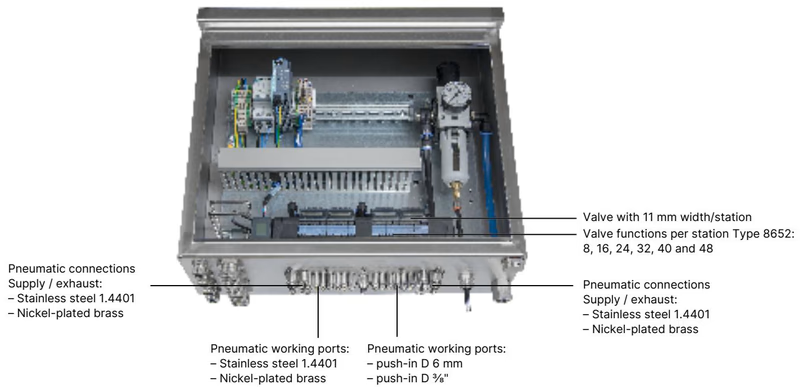
| Property | AirLINE Quick Configuration (20114261) |
|---|---|
| Adapter Plate Material | Anodised aluminium |
| Pneumatic Fitting Material | Nickel-plated brass |
| Supply / Exhaust Ports | Push-in D10 mm |
| Working Ports | Push-in D6 mm |
| Terminal Mounting Position | Control cabinet floor or control cabinet wall |
BURKERT 20114261 utilizes a Sub-D 9-pin female connector for PROFIBUS DPV1 communication alongside spring-loaded terminal connectors for electronic logic and solenoid valve power.
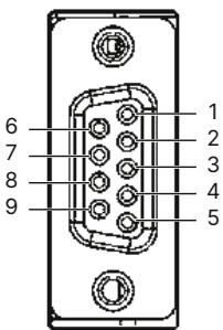
| Pin | Signal | Description |
|---|---|---|
| 1 | SHIELDING | Cable shielding connection |
| 2 | M24 | Ground 24 V (optional) |
| 3 | RxD/TxD-P | Receive / Transmit data positive (B-line) |
| 4 | CNTR-P | Repeater control signal positive (optional) |
| 5 | DGND | Data ground (reference potential for terminating resistor) |
| 6 | +5 V | Supply voltage (+5 V) for terminating resistor network |
| 7 | +24 V | Supply 24 V (optional) |
| 8 | RxD/TxD-N | Receive / Transmit data negative (A-line) |
| 9 | CNTR-N | Repeater control signal negative (optional) |
Power supply circuits are split between bus communication/display logic and the valve manifold outputs. Connection wiring is established through cage-clamp spring-loaded blocks accommodating conductor cross-sections up to 1.5 mm²:
All 24 valve positions are populated with Type 6534 double 3/2-way servo-controlled solenoid valve slices in Circuit Function D (normally open, with manual override). Each slice contains two independent pilot actuators powered by Type 6164 pilot solenoids.
| Parameter | Value |
|---|---|
| Circuit Function | CF D (2x 3/2-way, servo-controlled, normally open) |
| Nominal Diameter (DN) | 4.0 mm |
| Flow Rate QNn (Air) | 310 l/min |
| Pressure Range | Vacuum to 10 bar (with auxiliary pilot air 3 to 10 bar) |
| Valve Switching Time (Opening) | 15 ms (measured per ISO 12238) |
| Valve Switching Time (Closing) | 15 ms (measured per ISO 12238) |
| Operating Voltage | 24 V DC (100% continuous duty cycle) |
| Replacement Valve Article No. | 301375 (spare part kit reference REF_296032) |
Integrated Exhaust Check Valves
The exhaust channels 3 (R) and 5 (S) contain factory-fitted integrated check valves. These prevent sudden exhaust pressure surges generated by large process valves from cycling back into unactuated circuits and causing unintended movements.
BURKERT 20114261 is a 24-fold assembly equipped with an intermediate supply block. Mounting holes are formatted according to the AirLINE Quick interface layout.
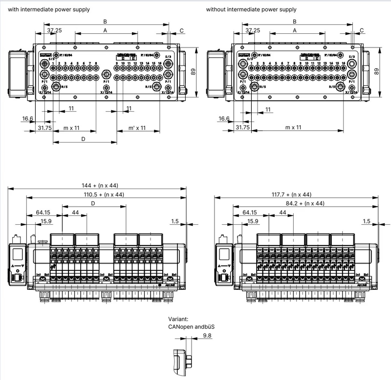
| Variant | A (mm) | B (mm) | C (Mounting Screws) | D (mm) | m | m' | n |
|---|---|---|---|---|---|---|---|
| 16-fold with intermediate supply | 112 | 224 | 10 x M5 | 114.3 | 7 | 7 | 4 |
| 20-fold with intermediate supply | 134 | 268 | 10 x M5 | 158.3 | 11 | 7 | 5 |
| 24-fold with intermediate supply (20114261) | 156 | 312 | 10 x M5 | 158.3 | 11 | 11 | 6 |
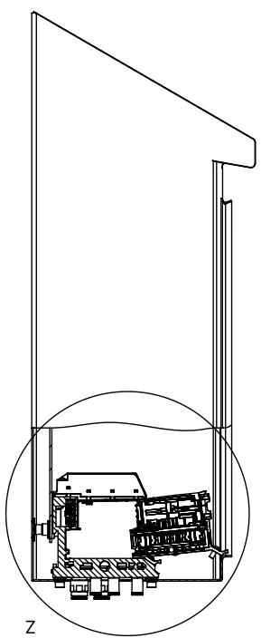
HotSwap Installation Clearance
When mounting inside an enclosure, maintain a minimum physical clearance between the valve island and the control cabinet door or front wall. This ensures sufficient mechanical clearance to withdraw, unclip, and replace a Type 6534 valve slice while the island remains under supply air pressure.
Type 8652 valve islands are certified for use in potentially explosive atmospheres under European, international, and regional directives when properly enclosed.
| Directive / Certification | Marking Code | Certificate Number |
|---|---|---|
| ATEX (Gas) | II 3G Ex ec IIC Gc | BVS 20 ATEX E 031 U |
| ATEX (Dust) | II 3D Ex tc IIIC Dc | BVS 20 ATEX E 031 U |
| IECEx (Gas & Dust) | Ex ec IIC Gc / Ex tc IIIC Dc | IECEx BVS 20.0024 U |
| North America (HazLoc) | Class I, Zone 2, AEx ec IIC Gc / Ex ec IIC Gc U; Class II, Zone 22, AEx tc IIIC Dc; Class I Div 2 Gr A, B, C, D; Class II, III Div 2 Gr F, G | cURus (PU17 code) |
| China Compulsory Certification | Ex ec IIC Gc / Ex tc IIIC Dc | SITIIAS / CCC (GB/T 3836) |
Hazardous Area Installation Conditions
Live Disconnection and HotSwap in Hazardous Atmospheres
Do not connect or disconnect electrical wiring terminals when energized in an explosive atmosphere. The pneumatic HotSwap feature must not be used while an explosive atmosphere is present unless the area has been verified and continuously monitored to be non-hazardous by qualified personnel.
| Accessory Description | Specification | Article No. |
|---|---|---|
| Replacement Valve Slice | Solenoid valve Type 6534, 2x 3/2-way CF-D, 24 V DC | 301375 (REF_296032) |
| Base Mounting Screw Set | M5 x 10 A2 DIN 6912 (10 pieces per pack) | 308661 |
| Height Adapter Plate | 24-fold AirLINE Quick with intermediate supply | 754964 |
| Retaining Plate (Cabinet Exterior) | 24-fold AirLINE Quick with intermediate supply | 60005570 |
| Blanking / Blind Plate | 24-fold AirLINE Quick with intermediate supply | 754969 |
| 5-Pin Spring Terminal | Power supply plug for bus communication and displays | 920180 |
| 2-Pin Spring Terminal | Power supply plug for pneumatic valve circuits (AUX 24 V) | 920442 |
| Gateway Module | Fieldbus gateway Type ME43 (PROFIBUS DP) | 301803 |
| Commissioning Tool Set | USB büS interface set 1 (Type 8923) for Bürkert Communicator | 772426 |
Explore similar products in our catalog


