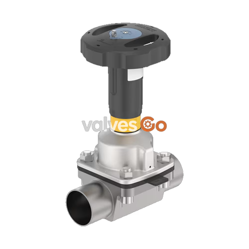
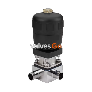
BURKERT 20115208 (Type 2973) is a manually operated 2/2-way FullFunction diaphragm shut-off valve engineered for sterile, hygienic, and aggressive media. Configured with a DN 50 (NPS 2) welded tube valve body (VP) made of forged-equivalent stainless steel pipe 316L / 1.4435 BN2 (tube dimensions 60.3 x 2.0 mm according to DIN EN ISO 1127 / ISO 4200 / DIN 11866 Series B), this unit incorporates a high-temperature EPDM diaphragm (size 50) rated for media temperatures from -10 °C to +143 °C and short-term steam sterilisation up to +150 °C for 60 minutes. The flow-optimised, zero-dead-leg geometry provides a nominal water flow coefficient of Kv = 70 m³/h (Cv = 81.6 gpm) across an operating pressure range of 0 to 10 bar (PN 10, ASME Class 150).
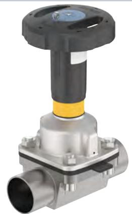
The Type 2973 manual actuator combines a PPS plastic handwheel (110 mm diameter, Size M) with a stainless steel 1.4308 diaphragm bonnet and 1.4305 spindle. The actuator assembly is autoclavable up to +150 °C for sterile processing environments. It features an optical position indicator with a 50-division reproducible stroke scale (2.0 mm pitch per rotation), an adjustable dual minimum and maximum stroke limiter, and an integrated 13-position locking pin mechanism with a 3.8 mm hole for padlock lockout. Compliance includes USP Class VI, FDA 21 CFR 177.2600, Regulation (EC) 1935/2004, and explosion protection under ATEX and IECEx (EPS 18 ATEX 2 008 X / IECEx EPS 18.0007X, II 2G Ex h IIC T4...T2 Gb, II 2D Ex h IIIC T135 °C...T300 °C Db).
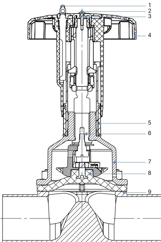
Component Materials and Construction
| Item | Element | Material |
|---|
| 1 | Lock pin | Stainless steel 1.4305 |
| 2 | Screw | Stainless steel A2 |
| 3 | Handwheel cover | Polyamide (PA) |
| 4 | Handwheel | Polyphenylene sulphide (PPS) |
| 5 | Visual position indicator | Polyamide (PA) |
| 6 | Valve spindle | Stainless steel 1.4305 |
| 7 | Diaphragm socket / bonnet | Stainless steel 1.4308 |
| 8 | Diaphragm | EPDM high-temperature (AD) (article code 688 427) |
| 9 | Valve body | Stainless steel pipe 316L / 1.4435 BN2 (Tube body VP) |
Technical Data and Dimensions
Actuator Dimensions (Diaphragm Size 50)
- Handwheel diameter (∅ B): 110 mm (Handwheel size M)
- Slope per full rotation: 2.0 mm
- Open position height H1 (to top of handwheel): 197 mm
- Open position height H2 (to top of position indicator): 203 mm
- Closed position height H3 (to top of handwheel): 173 mm
- Closed position height H4 (to top of position indicator): 179 mm
Tube Valve Body (VP) Welded Dimensions (DN 50)
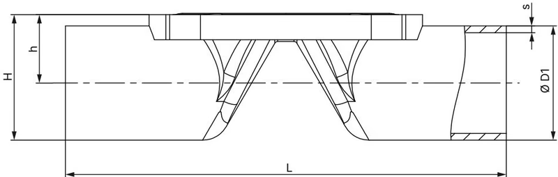
| Diaphragm Size | Port Connection DN | Outer ∅ D1 [mm] | Wall Thickness s [mm] | Face-to-Face L [mm] | Port Center Height h [mm] | Body Total Height H [mm] | Product Key |
|---|
| 50 | 50 (ISO pipe) | 60.3 | 2.0 | 192.0 | 35.35 | 65.50 | SA47 |
- Standard connection: DIN EN ISO 1127 / ISO 4200 / DIN 11866 series B
- Flow factor: Kv = 69.7 to 70.0 m³/h (water at +20 °C, Δp = 1 bar)
Stroke Limitation and Handwheel Locking
Type 2973 manual actuators include integrated stroke limitation and operational locking to safeguard the diaphragm against overcompression and control medium throughput.
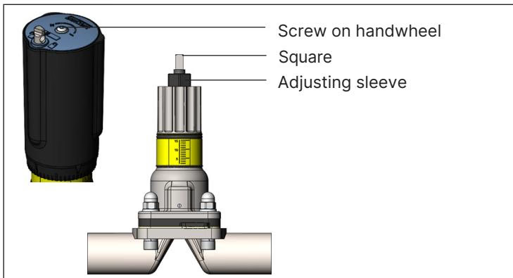
Setting Minimum and Maximum Stroke Limits
- Rotate the handwheel clockwise until the valve reaches the fully closed position.
- Loosen the handwheel screw (2 mm hexagon socket) and remove the handwheel.
- Turn the internal adjusting sleeve clockwise until it stops. The minimum stroke limit is now set.
- Reattach the handwheel, ensuring the square profile of the spindle and the hexagon head of the adjusting sleeve align with the internal handwheel geometry.
- Move the valve to the desired maximum open position.
- Loosen the handwheel screw again and remove the handwheel.
- Pull the adjusting sleeve upward while rotating it counterclockwise until it stops. The maximum stroke limit is now set.
- Reinstall the handwheel and tighten the securing screw to 0.9 Nm. If required for permanent retention, apply threadlocker.
Handwheel Lockout Procedure

For diaphragm sizes 32 to 50, the handwheel can be locked in 13 discrete positions per rotation (each 27° increment corresponds to 0.15 mm of axial stroke):
- Push the locking pin downward and rotate it by 180° (clockwise or counterclockwise) until it snaps into the locking notch.
- The locking pin incorporates a 3.8 mm diameter through-hole. When fully engaged, this hole clears the housing and accepts a standard padlock for lock-out/tag-out (LOTO) isolation.
Installation and Self-Draining Guidelines
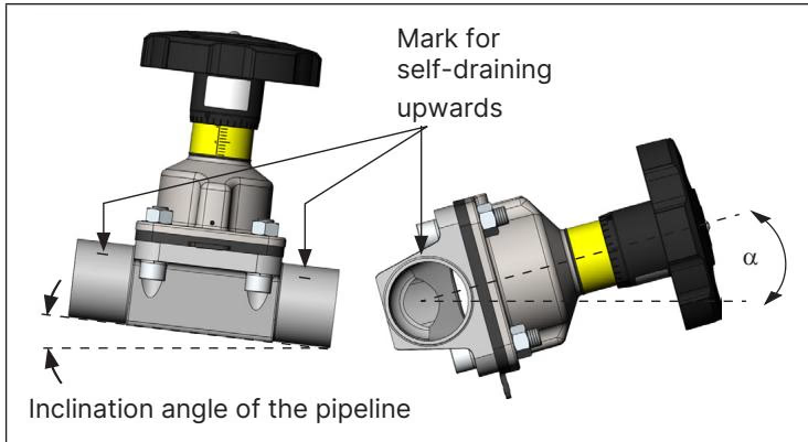
Pipeline Orientation and Leakage Monitoring
- The valve can be mounted in any orientation, preferably with the actuator upright.
- To ensure continuous leakage monitoring, rotate the actuator bonnet so that at least one relief bore faces the lowest gravitational point.
- Self-draining installation requires setting the pipeline and valve body to the specific self-draining angle α marked on the port connection of the tube valve body (VP). The port orientation marking must face upward.
Welding Precaution
Prior to welding the tube valve body into the pipeline, the actuator assembly and diaphragm must be completely removed from the body to avoid thermal destruction of the EPDM elastomer and actuator components:
- Rotate the handwheel counterclockwise to the full OPEN position.
- Loosen the four body fastening screws crosswise and lift the actuator and diaphragm away.
- Weld the valve body into the aligned, supported pipe system.
- Clean and inspect the body interior prior to reinstalling the actuator and diaphragm.
Tightening Torques and Assembly
Handwheel Tightening Torque (Medium Pressure: 10 bar)
| Diaphragm Size | Static Tightness (EPDM) | Dynamic Tightness (EPDM) |
|---|
| 50 | 6.0 Nm | 15.0 Nm |
- A tolerance of +10% applies to all handwheel tightening torques.
- Static tightness: Valve closed with medium pressure applied to one side.
- Dynamic tightness: Valve closed against active flow until leak-tight shut-off is achieved.
Body Fastening Screws
- Fastening torque for diaphragm size 50 on tube valve body (VP) with EPDM diaphragm: 15 Nm (+10% tolerance).
- Tighten screws crosswise in three progressive steps (approx. 5 Nm, 10 Nm, 15 Nm).
- When installing a size 50 EPDM diaphragm (threaded connection), screw the diaphragm hand-tight into the compressor, then back it off counterclockwise by one half-turn (180°) before mounting onto the body.
ATEX and IECEx Hazardous Area Safety (Code PX51)
Potential Electrostatic Charging Hazard
Under certificates EPS 18 ATEX 2 008 X and IECEx EPS 18.0007X (II 2G Ex h IIC T4...T2 Gb, II 2D Ex h IIIC T135 °C...T300 °C Db), observe the following:
- Electrically bond and ground the metallic valve body to the pipeline system to ensure equipotential bonding.
- Ground conductive parts using a grounding strap clamp or terminal at the dedicated grounding point.
- Clean actuator surfaces only with a damp or antistatic cloth to prevent electrostatic discharge.
- Fluid media conductivity limits per IEC 60079-32-1:
- Conductivity ≤ 100 pS/m: Permitted only if flow velocity ≤ 1 m/s or pipe dry-run monitoring is active.
- Conductivity > 100 pS/m to ≤ 1,000 pS/m: Permitted for particle-free liquids, steam, and clean gases.
- Conductivity > 1,000 pS/m: No restrictions.
| Temperature Class | Maximum Surface Temperature | Permissible Ambient Temperature | Maximum Medium Temperature |
|---|
| T4 | +135 °C | -40 °C to +100 °C | +125 °C |
| T3 | +200 °C | -40 °C to +130 °C | +185 °C |
| T2 | +300 °C | -40 °C to +130 °C | +285 °C |
Spare Parts and Ordering
- Replacement Diaphragm (Size 50, EPDM High-Temperature): Article number 688 427 (Material code EPDM E04, threaded connection).
- Complete Replacement Actuator: Order using valve article number 20115208 via the manufacturer portal.