

PN16

BURKERT 20116568 (Type 8652) is a 12-slot AirLINE Quick valve island with PROFIBUS DPV1, stainless steel D10/D6 ports, 2x 3/2-way CF-C valves, and -1 to 10 bar nominal pressure.
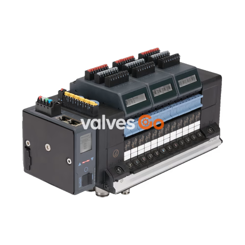
BURKERT 20116568 (Type 8652) is a modular AirLINE Quick valve island designed to control pneumatic loads such as process valves and pneumatic actuators in automation environments. This specific configuration features 12 valve slots populated with 2x 3/2-way CF-C valves, integrated into an AirLINE Quick stainless steel adapter interface with D10 stainless steel supply connections and D6 stainless steel working ports. Communication is provided via a PROFIBUS DPV1 fieldbus module using a Sub-D 9-pin hardware interface.
The assembly operates with an internal auxiliary pilot air supply, handling a nominal process pressure from -1.00 bar to 10.00 bar and a pilot pressure between 3.00 bar and 10.00 bar. Rated for medium and ambient temperatures from -10 °C to +55 °C, the unit conforms to protection class IP20 and features the Basic variant architecture without a local digital display.
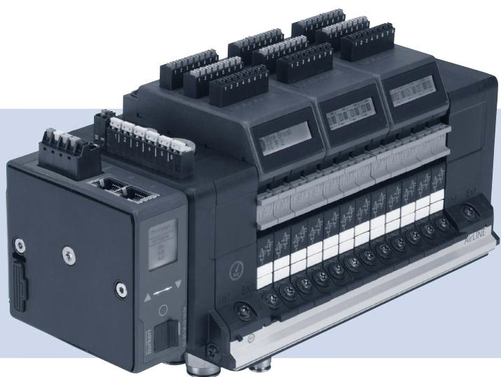
Article 20116568 integrates the following factory configuration parameters:
| Specification Parameter | Value |
|---|---|
| Type | 8652 |
| Article Number (SKU) | 20116568 |
| Product Variant | Basic (without display) |
| Modular Variant | Fieldbus module |
| Communication Protocol | PROFIBUS DPV1 |
| Communication Interface Hardware | Sub-D 9-pin |
| Total Valve Slots | 12 PCE |
| Valve Positions 1 to 12 | 2x 3/2-way CF-C (all 12 positions) |
| Supply Connection Size / Material | D10 / Stainless steel |
| Working Port Size / Material | D6 / Stainless steel |
| AirLINE Quick Interface Material | Stainless steel |
| Auxiliary Pilot Air | Internal |
| Additional Supplies (Left / Middle / Right) | Without |
| Nominal Pressure Min. / Max. | -1.00 bar / 10.00 bar (-1 bar to 10 bar) |
| Pilot Pressure Min. / Max. | 3.00 bar / 10.00 bar (3 bar to 10 bar) |
| Medium Temperature Min. / Max. | -10.00 °C / +55.00 °C |
| Ambient Temperature Min. / Max. | -10.00 °C / +55.00 °C |
| Digital Inputs | 0 (Electronic modules 1, 2, 3 without DI) |
| Integrated Check Valves in 3 (R) / 5 (S) | No / No |
| Pneumatic HotSwap in 1 (P) | No |
| Intermediate Feed Quantity | 0 PCE |
| Maximum Protection Class | IP20 (with suitable connection) |
Type 8652 AirLINE valve islands comply with ATEX Directive 2014/34/EU and North American standards (NEC 500, NEC 505, NEC 506) when ordered with explosion protection codes PU17 or PX68. The unit is designed for use in hazardous areas under the following classifications:
| Term | Meaning in Type 8652 Documentation |
|---|---|
| Actuators, process valves | Pneumatic loads controlled by the valve island |
| büS | Bürkert communication bus based on the CANopen protocol |
| EVS | External valve shutdown: valves can be de-energized independently of the bus master control signal on individual valves, modules, or the entire block |
| Hazardous area | Potentially explosive atmosphere |
| Device, valve island | Type 8652 AirLINE valve island |
| SIA version | Version for safety-related shutdown (see EVS) |
| Pneumatic valve, pilot control valve | Pneumatic spool valves integrated into the valve island assembly |
Valve islands designated for hazardous locations carry two nameplates: a standard product nameplate and an Ex certification nameplate.
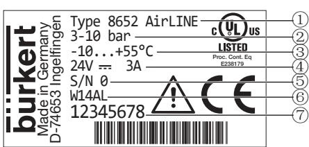
| Position | Description | Example Data |
|---|---|---|
| 1 | Device type | Type 8652 AirLINE |
| 2 | Pressure range | 3–10 bar |
| 3 | Ambient temperature range | -10 °C to +55 °C |
| 4 | Rated voltage / Current consumption | 24 V DC / 3 A |
| 5 | Serial number | S/N 0 (example) |
| 6 | Manufacturing code (encoded) | W14AL (example) |
| 7 | Device order number | Article number (e.g., 20116568) |
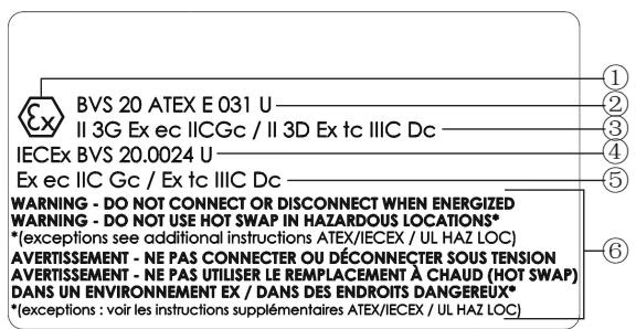
| Position | Description | Value (Code PX68) |
|---|---|---|
| 1 | Explosion protection symbol | Ex marking |
| 2 | ATEX certificate number | BVS 20 ATEX E 031 U |
| 3 | ATEX gas / dust protection marking | II 3G Ex ec IIC Gc / II 3D Ex tc IIIC Dc |
| 4 | IECEx certificate number | IECEx BVS 20.0024 U |
| 5 | IECEx gas / dust protection marking | Ex ec IIC Gc / Ex tc IIIC Dc |
| 6 | Safety advisory | Electrical connection and HotSwap conditions |
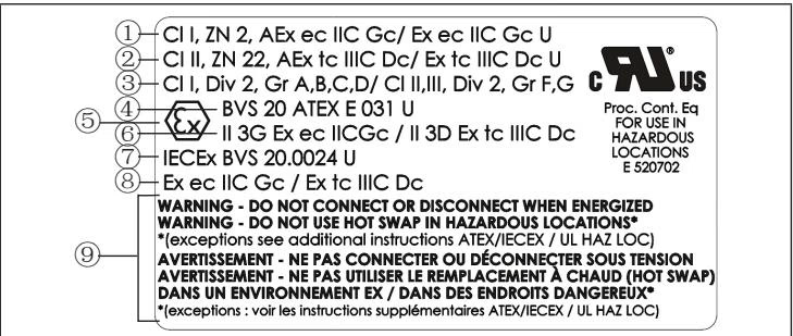
| Position | Description | Value (Code PU17) |
|---|---|---|
| 1 | Zone marking US/CA (Gas) | Cl I, ZN 2, AEx ec IIC Gc / Ex ec IIC Gc U |
| 2 | Zone marking US/CA (Dust) | Cl II ZN 22, AEx tc IIIC Dc / Ex tc IIIC Dc U |
| 3 | Division marking US/CA (Gas/Dust) | Cl I, Div 2, Gr A, B, C, D / Cl II, III, Div 2, Gr F, G |
| 4 | ATEX certificate number | BVS 20 ATEX E 031 U |
| 5 | Explosion protection symbol | Ex marking |
| 6 | ATEX gas / dust protection marking | II 3G Ex ec IIC Gc / II 3D Ex tc IIIC Dc |
| 7 | IECEx certificate number | IECEx BVS 20.0024 U |
| 8 | IECEx gas / dust protection marking | Ex ec IIC Gc / Ex tc IIIC Dc |
| 9 | Safety advisory | Electrical connection and HotSwap conditions |
Additional Warning Label
Shipments include duplicate adhesive labels marked: WARNING DO NOT CONNECT OR DISCONNECT WHEN ENERGIZED If cabinet installation obscures the safety information on the primary Ex nameplates, affix this additional label in a clearly visible position on the valve island.
| Parameter | Specification |
|---|---|
| Rated Operating Voltage | 24 V DC ±10% |
| Nominal Power Consumption | Dependent on configuration |
| Ambient Temperature Range | -10 °C to +55 °C |
| Pilot Solenoid Valve Type | Type 6164 (pilot element for Type 6534 pneumatic valve) |
| Maximum Number of Valve Slice Functions | 48 functions |
When a configuration uses fewer than 48 valve slice functions, the converted electrical power is lower, resulting in equal or lower operating temperatures.
At a maximum ambient temperature of +55 °C inside the control cabinet, the system does not exceed the limits of temperature class T4. When the AirLINE Quick adapter interface is mounted through the cabinet wall or bottom plate, the external surface operating temperature does not exceed 80 °C.
Permissible configurations in hazardous areas include up to 48 valve slice functions using Type 6534 or Type 6534 SIA valves, external valve shutdown (EVS), electronic modules with digital inputs, and connection modules with integrated pressure sensors.
Cabinet Installation Requirements
For installation in hazardous areas, Type 8652 must be installed inside a certified enclosure:
Electrical Isolation in Explosive Atmospheres
To prevent electrical ignition hazards:
HotSwap Restrictions
The HotSwap function is prohibited in potentially explosive atmospheres unless an explosive atmosphere is verified absent by suitable testing equipment. Article 20116568 is configured without pneumatic HotSwap in port 1 (P).
Electrostatic Protection and Mechanical Handling
Sudden electrostatic discharge poses an ignition hazard in potentially explosive atmospheres. Clean external surfaces only with a damp or anti-static cloth. Do not apply mechanical loads or use the valve island assembly as a step. Repairs must be conducted exclusively by the manufacturer.
Explore similar products in our catalog


