

PN16

BURKERT 20121017 (Type 8652) AirLINE is a 20-slot pneumatic valve island with PROFINET S2 system redundancy, AirLINE Quick aluminium plate, 40 digital inputs, brass D10/D6 ports, and hot-swap support.
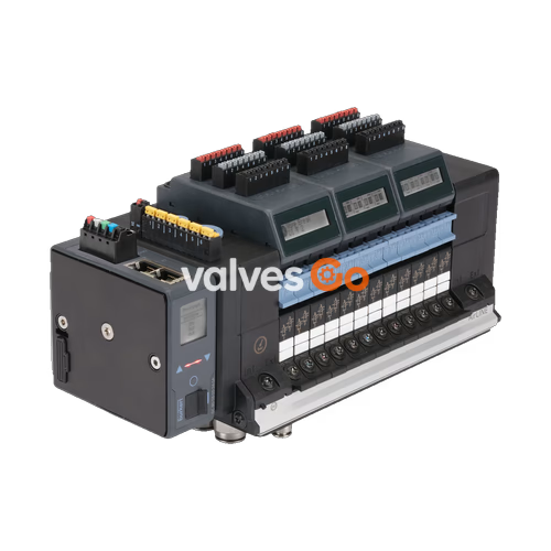
BURKERT 20121017 (Type 8652) is an electropneumatic valve island engineered specifically for process automation requirements. This factory configuration combines a 20-slot pneumatic base, PROFINET S2 communication interface with system redundancy, an AirLINE Quick anodised aluminium floor adapter plate, brass push-in fittings (D10 supply and D6 working ports), and 40 integrated digital inputs distributed across five 8DI electronic modules.

Pneumatic reliability is supported by integrated check valves inside exhaust ducts 3 (R) and 5 (S), preventing accidental actuator motion caused by system backpressure peaks. An integrated pneumatic HotSwap function at supply port 1 (P) permits valve replacement under live operating pressure with a flow rate reduction of approximately 3%.
Article 20121017 integrates 20 physical valve positions and one intermediate supply and exhaust feed module, populated with pilot-operated solenoid valves and blind plates:
| Slot Position | Valve Function | Circuit Type | Operating State | Manual Override |
|---|---|---|---|---|
| Position 1 | 3/2-way solenoid valve | CF-C (normally closed) | Servo-controlled | Latching / spring return |
| Position 2 | 3/2-way solenoid valve | CF-C (normally closed) | Servo-controlled | Latching / spring return |
| Position 3 | 3/2-way solenoid valve | CF-C (normally closed) | Servo-controlled | Latching / spring return |
| Position 4 | 3/2-way solenoid valve | CF-C (normally closed) | Servo-controlled | Latching / spring return |
| Position 5 | 5/2-way solenoid valve | CF-H (monostable) | Servo-controlled | Latching / spring return |
| Position 6 | 5/2-way solenoid valve | CF-H (monostable) | Servo-controlled | Latching / spring return |
| Position 7 | 5/2-way solenoid valve | CF-H (monostable) | Servo-controlled | Latching / spring return |
| Position 8 | 5/2-way solenoid valve | CF-H (monostable) | Servo-controlled | Latching / spring return |
| Position 9 | 5/2-way solenoid valve | CF-H (monostable) | Servo-controlled | Latching / spring return |
| Position 10 | 5/2-way solenoid valve | CF-H (monostable) | Servo-controlled | Latching / spring return |
| Position 11 | 5/2-way solenoid valve | CF-H (monostable) | Servo-controlled | Latching / spring return |
| Position 12 | 5/2-way solenoid valve | CF-H (monostable) | Servo-controlled | Latching / spring return |
| Position 13 | 5/2-way solenoid valve | CF-H (monostable) | Servo-controlled | Latching / spring return |
| Position 14 | 5/2-way solenoid valve | CF-H (monostable) | Servo-controlled | Latching / spring return |
| Position 15 | 5/2-way solenoid valve | CF-H (monostable) | Servo-controlled | Latching / spring return |
| Position 16 | 5/2-way solenoid valve | CF-H (monostable) | Servo-controlled | Latching / spring return |
| Position 17 | 5/2-way solenoid valve | CF-H (monostable) | Servo-controlled | Latching / spring return |
| Position 18 | Blind plate | — | Unassigned slot | — |
| Position 19 | Blind plate | — | Unassigned slot | — |
| Position 20 | Blind plate | — | Unassigned slot | — |
| Specification Parameter | Value / Characteristic |
|---|---|
| Operating medium | Oil-free or lubricated compressed dry air, neutral gases (5 µm filter recommended) |
| Compressed air quality | ISO 8573-1:2010, Class 7.4.4 |
| Nominal operating pressure | -1.00 bar to 10.00 bar (vacuum to 10 bar) |
| Auxiliary pilot air | Internal supply, 3 bar to 10 bar |
| Nominal flow rate QNn (air) | 310 l/min (measured at +20 °C, 6 bar inlet pressure, 1 bar pressure drop) |
| Flow rate with HotSwap engaged | Reduced by approx. 3 % |
| Switching times (ISO 12238) | CF-C: opening 15 ms, closing 15 ms; CF-H: opening 20 ms, closing 25 ms |
| Operating voltage | 24 V DC (±10 %), residual ripple 1 Vss |
| Power consumption per valve | 0.7 W nominal (0.175 W after internal holding power reduction) |
| Nominal current per valve | 29 mA (10 mA after power reduction) |
| Operating duty cycle | Continuous operation (100 % ED) |
| Electrical protection class | Class III according to DIN EN 61140 / VDE 0140 |
| Degree of protection | IP20 (bare module); IP65 in closed control cabinet via AirLINE Quick adapter |
| Ambient & medium temperature | -10 °C to +55 °C |
| Storage temperature | -20 °C to +60 °C |
| Housing material | Polyamide (PA) |
| Sealing materials | NBR and PUR |
| Station slice width | 11 mm |
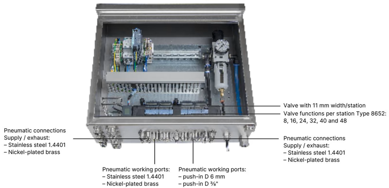
The AirLINE Quick aluminium adapter plate enables direct mounting through the floor or wall cutout of a control cabinet. All pneumatic supply and working lines connect on the cabinet exterior, eliminating bulkheads and internal piping while achieving an IP65 seal against the cabinet enclosure.
| Mechanical / Interface Item | Execution Detail |
|---|---|
| Adapter plate material | Anodised aluminium |
| Working pneumatic ports (2 & 4) | Push-in fittings D6 mm, nickel-plated brass |
| Supply / exhaust connections (1, 3, 5) | Push-in fittings D10 mm, nickel-plated brass |
| Installation location | Control cabinet floor or control cabinet wall |
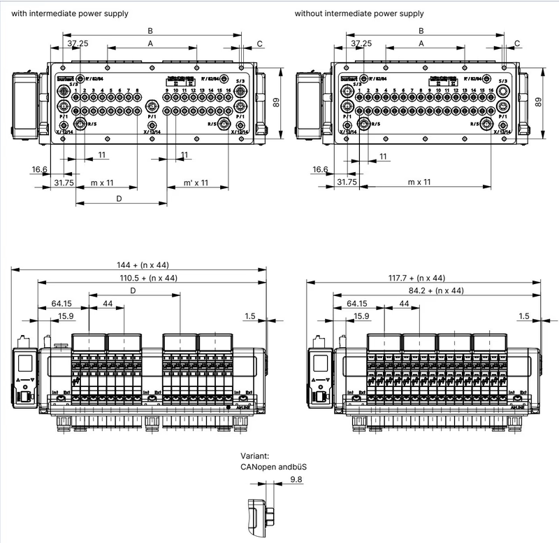
Dimensions for the 20-fold variant with integrated intermediate supply module:
| Dimension Variable | Dimension Value (mm) |
|---|---|
| A | 134 mm |
| B | 268 mm |
| C | 10 × M5 fastening screws |
| D | 158.3 mm |
| m | 11 |
| m' | 7 |
| n | 5 |
Mounting Clearances
Maintain the prescribed minimum clearance between the valve island front edge and the control cabinet door or frame. This clearance ensures sufficient space for unlatching and withdrawing pilot valves during HotSwap servicing without dismounting the terminal.
Type 8652 utilizes separated electrical feeds for logic and valve coils. The electronics and LC display are powered via a 5-pin spring-loaded terminal block, while valve coils receive power via a separate 2-pin spring-loaded terminal block:
| Terminal | Pin / Clip | Wire Colour Code | Signal Assignment |
|---|---|---|---|
| Logic Supply (5-pin) | 1 | Red | +24 V DC logic power |
| Logic Supply (5-pin) | 2 | White | CAN_H (büS interface) |
| Logic Supply (5-pin) | 3 | Green | Shielding |
| Logic Supply (5-pin) | 4 | Blue | CAN_L (büS interface) |
| Logic Supply (5-pin) | 5 | Black | 0 V DC (GND) |
| Valve Power (2-pin) | 1 | Red | AUX +24 V DC (valves) |
| Valve Power (2-pin) | 2 | Black | 0 V DC (GND) |
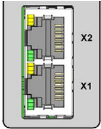
PROFINET S2 communication connects through dual RJ45 Ethernet ports (X1 and X2), providing media and system redundancy:
| RJ45 Pin | PROFINET Signal Assignment |
|---|---|
| Pin 1 | TX+ (Transmit Data +) |
| Pin 2 | TX- (Transmit Data -) |
| Pin 3 | RX+ (Receive Data +) |
| Pin 4 | Not connected (N.C.) |
| Pin 5 | Not connected (N.C.) |
| Pin 6 | RX- (Receive Data -) |
| Pin 7 | Not connected (N.C.) |
| Pin 8 | Not connected (N.C.) |
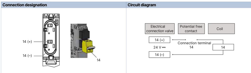
Article 20121017 features 5 electronic modules with digital inputs, delivering 40 feedback channels directly over PROFINET S2. Each input channel supports standard 2-wire sensors, 3-wire sensors, and mechanical dry contacts:
| Parameter | Technical Specification |
|---|---|
| Number of digital input channels | 40 DI total (5 modules × 8 DI) |
| Supported sensor types | 2-wire PNP/NPN (10–30 V), 3-wire PNP/NPN, mechanical limit switches |
| Switching thresholds | V_OFF = 0 V to 5 V; V_ON = 10 V to 30 V |
| Input current at V_ON | Max. 5.7 mA per channel (typical at 24 V DC) |
| Current supply per DI | Max. 30 mA per channel |
| Input impedance | > 4 kΩ |
| Diagnostic detection | Open-circuit detection with 2-wire sensors; short-circuit detection with 3-wire sensors |
| Galvanic isolation | None (all channels share common reference potential) |
| Maximum cable length | < 30 m (conductor cross-section ≤ 1.5 mm²) |
Each valve slot features an automatic shut-off check valve at the supply port P (1). Removing a valve for maintenance isolates pilot pressure to that station, preventing line decompression and maintaining process availability on adjacent active slots.
Hazardous Area Limitations
In potentially explosive atmospheres (ATEX Zone 2 / 22 or Class I, Div 2), hot-swapping valves and disconnecting electrical plug connections are strictly prohibited while energized, unless the atmosphere has been verified to be non-explosive by authorized personnel.
Individual valve positions can be replaced using Burkert Type 6534 replacement modules:
| Circuit Function | QNn (Air) | Pressure Range | Opening Time | Closing Time | Operating Voltage | Replacement Article No. |
|---|---|---|---|---|---|---|
| CF-C (3/2-way NC) | 270 l/min | Vac to 10 bar | 15 ms | 15 ms | 24 V DC | 301374 (REF 296031) |
| CF-H (5/2-way mono) | 290 l/min | Vac to 10 bar | 20 ms | 25 ms | 24 V DC | 301376 (REF 296033) |
| Blind Plate Valve | — | — | — | — | — | 335779 (REF 327614) |
Explore similar products in our catalog


