Type 2032

BURKERT 20121245 (Type 2933) manually operated 2/2-way diaphragm valve. Features forged stainless steel 316L body, clamp connection, and PTFE/EPDM diaphragm.
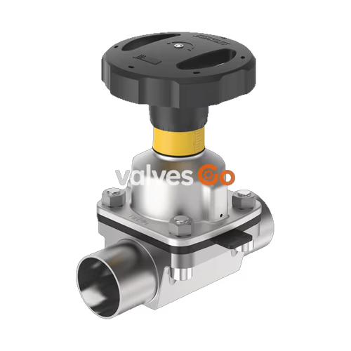
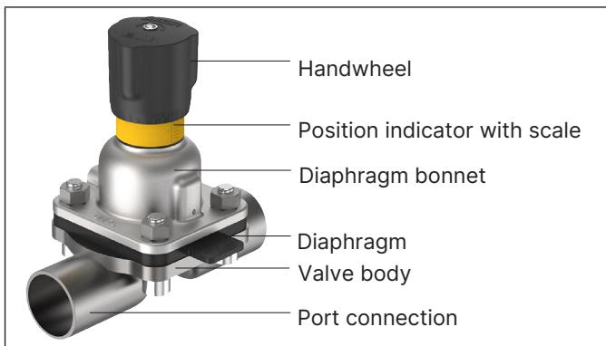
BURKERT 20121245 (Type 2933) is a manually operated 2/2-way diaphragm valve designed for hygienic and aggressive ambient conditions. It consists of a manual actuator with a plastic or stainless steel handwheel, a PTFE/EPDM diaphragm, and a flow-optimized 2-way forged stainless steel valve body. The minimum dead space design enables high flow values and a wide range of possible applications in the food, beverage, biotechnology, and pharmaceutical industries. The actuator features a compact, autoclavable design equipped with an integrated visual position indicator, a reproducible stroke scale, and an adjustable closing limiter.
| Product properties | Description |
|---|---|
| Valve body material | Forged stainless steel 1.4435 in accordance with BN2 DIN EN 10222-5, F316L in accordance with ASTM A182/A182M and 316L in accordance with ASME BPE |
| Diaphragm material | PTFE with EPDM backing membrane (EA) |
| Actuator material | Stainless steel/PPS, PPS/PPS, stainless steel/stainless steel |
| Standard surface quality | Internally electrically polished: Ra ≤ 0.38 μm (ASME BPE SF4 / DIN HE4) |
| Operating medium | Neutral gases and liquids, highly purified, sterile, aggressive or abrasive media |
| Medium temperature | -10 to +130 °C (steam sterilisation +140 °C for 60 min) |
| Ambient temperature | -10 to +130 °C (short-term up to +150 °C), autoclavable |
By manually overriding the handwheel, the force is transmitted via a spindle and the valve is opened or closed. Turning the handwheel anticlockwise opens the valve, turning it clockwise closes it.
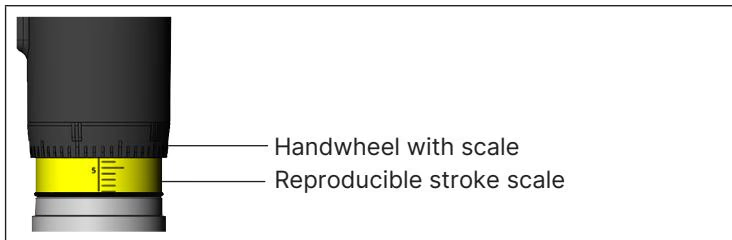
Turning the handwheel counterclockwise reveals the yellow position indicator and the scale marked on it as the valve opens further. The stroke scale shows the relative position of the valve and serves as a fixation point for determining the rotation position.
TIP
To protect the actuator, we recommend not closing the actuator with more force than is required to close the valve tightly.
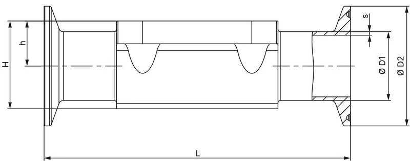
ASME BPE Dimensions (mm)
| Diaphragm size | Port connection Inch | ∅D1 | s | ∅D2 | L | h | H |
|---|---|---|---|---|---|---|---|
| 8 | 1/4" | 6.35 | 0.89 | 25.0 | 64.5 | 5.7 | 15.2 |
| 8 | 3/8" | 9.53 | 0.89 | 25.0 | 89 | 5.7 | 15.2 |
| 8 | 1/2" | 12.7 | 1.65 | 25.0 | 89 | 9.3 | 18.8 |
| 15 | 1/2" | 12.7 | 1.65 | 25.0 | 108 | 8.15 | 19.85 |
| 15 | 3/4" | 19.05 | 1.65 | 25.0 | 89 | 12.05 | 23.75 |
| 20 | 3/4" | 19.05 | 1.65 | 25.0 | 117 | 16 | 30.3 |
| 25 | 1" | 25.4 | 1.65 | 50.5 | 127 | 19 | 37 |
| 40 | 1 1/2" | 38.1 | 1.65 | 50.5 | 159 | 27.6 | 52.4 |
| 50 | 2" | 50.8 | 1.65 | 64.0 | 190 | 35.5 | 68.3 |
| Diaphragm size | Port connection (ASME BPE) | Kv value water [m³/h] |
|---|---|---|
| 8 | 1/4" | 0.7 |
| 8 | 3/8" | 1.6 |
| 8 | 1/2" | 1.5 |
| 15 | 1/2" | 3.1 |
| 15 | 3/4" | 6.5 |
| 20 | 3/4" | 8.4 |
| 25 | 1" | 15.5 |
| 40 | 1 1/2" | 37 |
| 50 | 2" | 66 |
| Diaphragm size | Max static operating pressure [bar] | Tightening torque for PTFE [Nm] |
|---|---|---|
| 8 | 10 | 1.1 |
| 15 | 10 | 1.7 |
| 20 | 10 | 3 |
| 25 | 10 | 3.5 |
| 32 | 10 | 4 |
| 40 | 10 | 7 |
| 50 | 10 | 11 |
WARNING
The tightening torques refer to the static media pressures specified above. Excessive torque can shorten the service life of the diaphragm. A tolerance of +10% applies to the tightening torques specified.
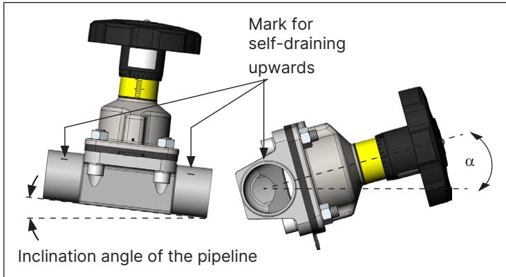
It is the responsibility of the installer and the operator to ensure self-draining. Observe the rules for self-draining during installation:
Explore similar products in our catalog