Type 2032

Burkert Type 2973 2/2-way manual diaphragm valve features a flow-optimized stainless steel or plastic body, PPS handwheel, and optical position indicator for hygienic applications up to 10 bar.
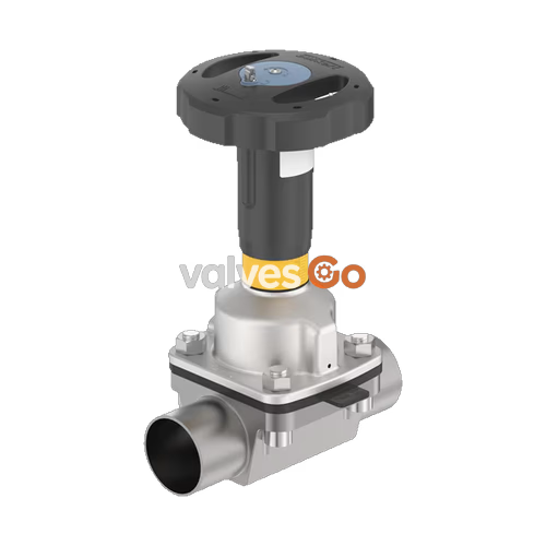
Burkert Type 2973 manually operated diaphragm valve consists of a manually operated actuator, a diaphragm, and a 2-way body. The manual actuator with a polyphenylene sulphide (PPS) handwheel ensures use in hygienic or aggressive ambient conditions. The flow-optimized valve body with minimum dead space enables high flow values and a wide range of possible applications. The actuator has a compact, autoclavable design and possesses a visual position indicator with a reproducible stroke scale. The actuator also features an adjustable minimum and maximum stroke limitation and a locking mechanism.
The device complies with the following approvals and conformities (depending on the variant):
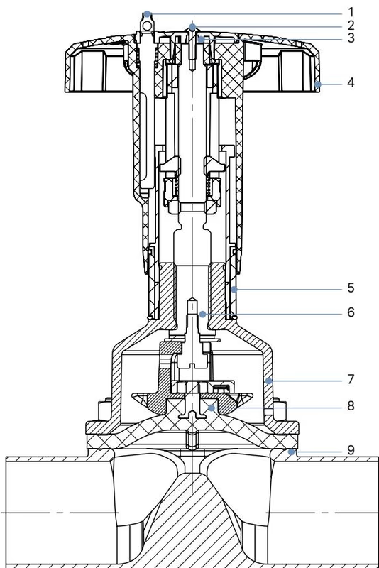
| No. | Element | Material |
|---|---|---|
| 1 | Lock pin | Stainless steel 1.4305 |
| 2 | Screw | Stainless steel A2 |
| 3 | Handwheel cover | Polyamide (PA) |
| 4 | Handwheel | Polyphenylene sulphide (PPS) |
| 5 | Visual position indicator | Polyamide (PA) |
| 6 | Valve spindle | Stainless steel 1.4305 |
| 7 | Diaphragm socket | Stainless steel 1.4308 |
| 8 | Diaphragm | EPDM (AD), PTFE/EPDM (EA), Advanced PTFE/EPDM (EU), Laminate of GYLON and EPDM (ER) |
| 9 | Valve body | Forged steel, Tube, Cast, or Plastic (PVC-C, PVC-U, PP, PVDF) |
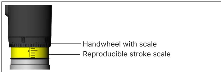
By manually overriding the handwheel, the force is transmitted via a spindle and the valve is opened or closed. Turning the handwheel counterclockwise opens the valve, revealing the yellow position indicator and the scale marked on it as the valve opens further.
The maximum permitted medium pressure depends on the diaphragm size and material.
| Diaphragm size | Maximum static operating pressure [bar] |
|---|---|
| 8 to 40 | 10 |
| 50 | 7 (for PPS handwheel) / 10 |
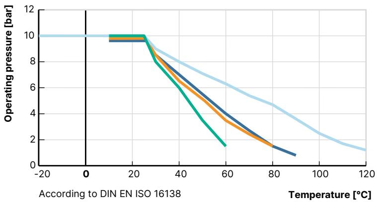
Observe the permissible operating pressure depending on the medium temperature for plastic valve bodies.
WARNING
Risk of injury due to high pressure and escaping medium. Switch off the pressure before working on the device or system. Vent or empty the lines.
The installation position can be any, but preferably with the actuator facing up. It is the responsibility of the installer and the operator to ensure self-draining.

A minimum and maximum stroke limit can be set for Type 2973 (diaphragm sizes 15 to 50) using an adjusting sleeve.
A locking mechanism is available to prevent accidental or unauthorized operation. The locking pin has a bore (Ø 3.8 mm) and can be secured with a padlock. Push the locking pin down and rotate by 180° to lock.
Explore similar products in our catalog