PN16

BURKERT 20122300 Type 8640 modular valve island with 16x 3/2 valve function C. Features 11 mm width per station, AirLINE Quick mounting, and collective socket module.
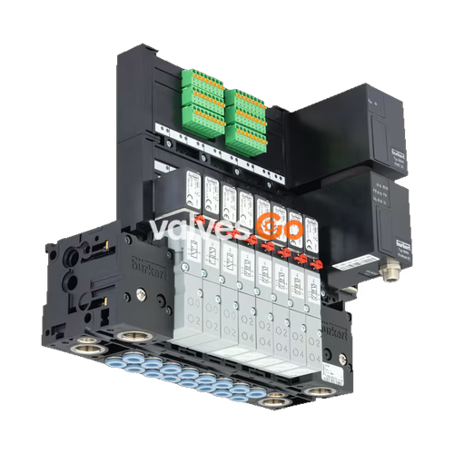
BURKERT 20122300 Type 8640 is a modular valve island for pneumatics featuring a compact design and modular configuration. This specific model utilizes an 11 mm width per station, a collective socket module, and AirLINE Quick mounting to provide higher flexibility in the control cabinet. It is equipped with 16x 3/2 valve function C capabilities, operating within a nominal pressure range of 2.5 to 10 bar.
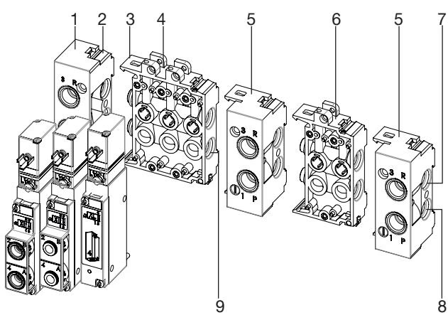
The Type 8640 valve unit system is designed to solve diverse and complex control problems due to its systematic modular construction and combination of pneumatic and electrical interfaces. By putting together a row of pneumatic modules with different numbers of valves, multiple valve functionalities may be realized on one valve unit. Bodies and connection modules are made of high-quality plastic (polyamide) and are easy to assemble by means of built-in snap connectors.

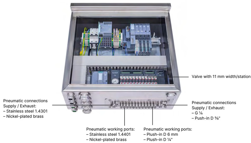
AirLINE Quick considerably reduces the use of components in the control cabinet. With the AirLINE Quick Adapter, the valve terminal is adapted directly to the control cabinet floor or control cabinet wall.
Advantages:
This model utilizes a collective connection module for electrical interfacing.
| Module | Description |
|---|---|
| Collective connection module | Connection via individual stranded wires Looped-through ground potential Max. 24 valves Degree of protection IP20 Screw-type terminals |
| No. | Element |
|---|---|
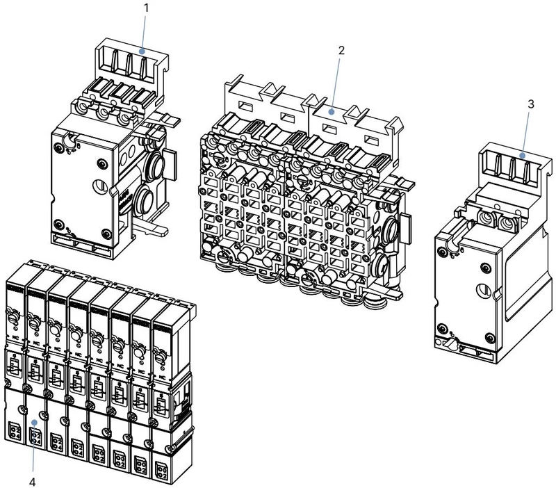
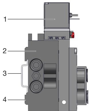
| 1 | Pneumatic connection module, left |
| 2 | Basic pneumatic modules |
| 3 | Pneumatic connection module, right |
| 4 | Valves (for example 5/2-way) |
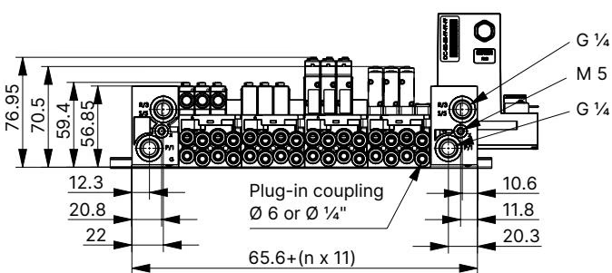
Pneumatics 11 mm width per station(Dimensions in mm, unless otherwise stated)
DANGER!
Risk of injury due to high pressure and escaping medium.
Risk of injury due to electric shock.
WARNING!
Risk of injury from quickly accelerating device parts and unconnected compressed air hoses flapping around.
NOTE
Crushed O-rings and profile seals lead to leaky blocks. Fasten each valve to the base module with 2 screws. Recommended tightening torque 0.6 ±0.1 Nm.
Standard rail installation:
Wall installation:
Explore similar products in our catalog