

PN16

Burkert 20122679 Type 8640 is a 5-bank pneumatic valve block with 33 mm add-on dimension, G 1/2 pressure port, G 1/4 working ports, 3 to 10 bar operating pressure, and DIN-rail mounting for single-wiring systems.
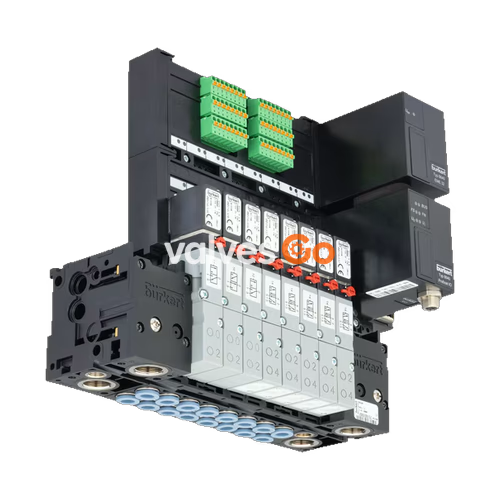
Burkert 20122679 Type 8640 is a pre-configured 5-bank modular pneumatic valve block designed for DIN-rail installation in control cabinets and process automation systems. Engineered with an add-on pitch dimension of 33 mm per station, article 20122679 provides a central G 1/2 supply pressure port (P / 1) and dedicated G 1/4 working connection ports positioned directly opposite the supply side. Operating across a nominal pressure span of 3 bar to 10 bar and a medium temperature range of 0 °C to 50 °C, this unit utilizes an individual single-wiring architecture without internal bus communication, rated to IP20 protection.

Article 20122679 provides a pre-assembled pneumatic base for discrete valve actuation. The mechanical layout groups 5 valve positions on a common manifold rail, routing pressurized air to actuator outlets while segregating pilot exhaust.
| Attribute Group | Specification Parameter | Value |
|---|---|---|
| Identity | Article Number / SKU | 20122679 |
| Identity | Model / Type | 8640 |
| Setup | Configuration | 33 mm 5-bank (5 valve stations) |
| Setup | Add-on Dimension 1 | 33 mm |
| Process Connection | Pressure Port 1 (P) | G 1/2 |
| Process Connection | Working Ports 2 (B) / 4 (A) | G 1/4 |
| Process Connection | Working Connection Position | Opposite of supply side |
| Pressure Limits | Nominal Operating Pressure | 3.00 bar to 10.00 bar |
| Temperature Limits | Medium Temperature | 0.00 °C to +50.00 °C |
| Temperature Limits | Ambient Temperature | 0.00 °C to +70.00 °C |
| Electrical Interface | Communication Version | Without (due to single wiring) |
| Electrical Interface | Internal Bus Communication | Without (due to single wiring) |
| I/O Capacity | Digital Inputs | 0 PCE |
| Manifold Features | Intermediate Feed Quantity | 0 PCE |
| Manifold Features | Manual/Automatic Switching | No |
| Manifold Features | Integrated Check Valves in 3 (R) / 5 (S) | No |
| Manifold Features | Pneumatic HotSwap in 1 (P) | No |
| Protection & Mounting | Enclosure Rating | IP20 (max. with suitable connector) |
| Protection & Mounting | Mounting Type | DIN-rail installation |
Single Wiring System Design
Article 20122679 is configured for discrete parallel wiring of individual valve coils. It contains no internal communication modules, fieldbus nodes, or digital input feedback cards. Each installed valve is addressed directly via external cabling.
The Type 8640 system combines polyamide bodies and modular manifold blocks using integrated snap connectors. Multi-block units interlock horizontally via upper and lower latching mechanisms, sealed at each interface by elastomer O-rings.
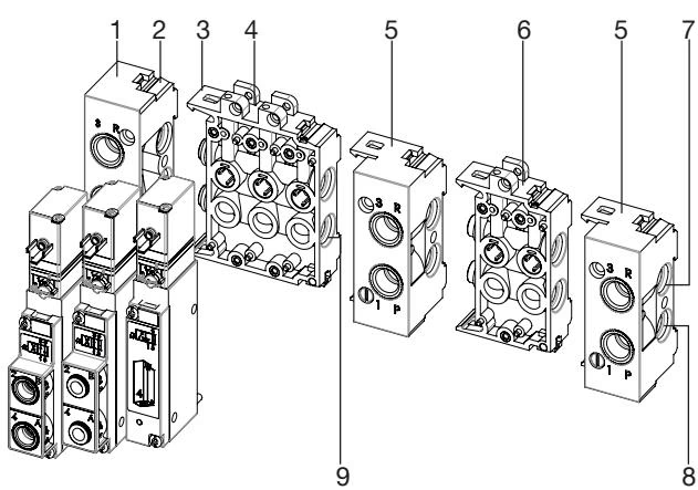
| Item | Designation | Functional Description |
|---|---|---|
| 1 | Left Connection Module | Primary pneumatic entry and exhaust block termination |
| 2 | Latch Tab | Upper retention tab for module interlocking |
| 3 | Latch Hook | Lower mechanical hook engaging the preceding module groove |
| 4 | Base Modules (3-fold) | Triple-station valve mounting sub-base |
| 5 | Right Connection Module | End block termination; allows multi-pressure staging or auxiliary feed |
| 6 | Base Modules (2-fold) | Dual-station valve mounting sub-base |
| 7 | Exhaust Channel 3 (R) | Common vent pathway for discharged pilot and actuator air |
| 8 | Supply Channel 1 (P) | Common pressurized header feeding all valve stations |
| 9 | O-Ring Seals | Interface boundary seals preventing inter-module leakage |
Seal Positioning Caution
Crushed, pinched, or missing O-rings and profile seals between module blocks cause immediate internal and external air leakage. Always inspect seal seating before latching modules.
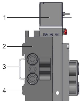
Burkert Type 8640 valve blocks support direct panel mounting or installation on standard DIN mounting rails in accordance with EN 50022 (35 x 7.5 mm or 35 x 15 mm).
When securing fittings into the pneumatic port connections, observe the recommended torque limits to prevent thread damage in the polyamide manifold bodies.
| Port Size | Port Marking / Function | Recommended Torque (Nm) | Maximum Torque (Nm) |
|---|---|---|---|
| G 1/4, NPT 1/4 | P, R/S Supply and Exhaust | 4 to 7 | 20 |
| G 1/8, NPT 1/8 | P, R/S Connection, A/B Outlets | 3 to 6 | 7 |
Pneumatic lines must meet DIN ISO 14743:2020 specifications to ensure holding capacity and pressure tightness under operating conditions from 3 to 10 bar.
| Hose Material | Hose Outside Diameter (mm) | Permitted Deviation (mm) |
|---|---|---|
| Polyamide (PA) | 3 to 10 | ±0.08 |
| Polyamide (PA) | 12 to 16 | ±0.10 |
| Polyurethane (PU) | 3 to 8 | ±0.10 |
| Polyurethane (PU) | 10 to 16 | ±0.15 |
According to DIN ISO 14743:2020, connected tubing must withstand the minimum holding forces listed below:
| Hose OD (mm) | 3 (1/8") | 4 (5/32") | 6 (1/4") | 8 (5/16") | 10 (3/8") | 12 (1/2") | 14 | 16 (5/8") |
|---|---|---|---|---|---|---|---|---|
| Min. Tensile Force PA (N) | 60 | 70 | 120 | 170 | 250 | 300 | 300 | 350 |
| Min. Tensile Force PU (N) | 25 | 50 | 100 | 150 | 200 | 200 | 250 | 300 |
Support Sleeve Usage
When utilizing flexible polyurethane (PU) tubing, install support sleeves (ID 20099400) inside the hose ends to maintain circular profile geometry and optimize grip.
Manifold stations accommodate various pilot and main valve functions, including 3/2-way, 4/2-way, 5/2-way, and 5/3-way configurations.
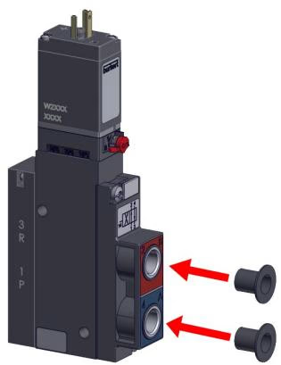
A 4/2-way valve installed on the block can be adapted into a 3/2-way function by sealing one of the active working ports with an airtight plug.
| Port 2 Status | Port 4 Status | Resulting Circuit Function | Operating State Description |
|---|---|---|---|
| Closed with plug | Open | Function C (Normally Closed) | Rest position: Port 1 closed, Port 4 vented to exhaust 3 |
| Open | Closed with plug | Function D (Normally Open) | Rest position: Port 1 connected to Port 2, exhaust 3 closed |
Valves include a mechanical manual override on the pilot stage:
Electrical Safety
Operate the manual override only when the electrical supply is switched off. Unlock all manual overrides prior to placing the system into remote electrical service.
Pressure and Voltage Hazard
Before opening pneumatic fittings or servicing electrical plugs, depressurize supply channel 1 (P), vent connected working lines, and disconnect control voltage.
| Fault Symptom | Probable Cause | Corrective Action |
|---|---|---|
| Valves fail to actuate | Operating voltage missing or below tolerance | Verify coil voltage against nameplate; check connector continuity. |
| Valves fail to actuate | Manual override locked in engaged position | Rotate manual override 90 degrees counter-clockwise to zero position. |
| Valves fail to actuate | Supply pressure below operating threshold | Restore supply pressure to at least 3 bar (minimum pilot threshold). |
| Delayed switching or continuous venting at exhaust | Main header pressure volume insufficient | Increase supply line cross-section; inspect upstream filters and regulators. |
| Delayed switching or continuous venting at exhaust | Exhaust silencers clogged with dirt or undersized | Clean exhaust silencer elements or replace with higher flow silencers. |
| Delayed switching or continuous venting at exhaust | Particulate contamination inside valve pilot stage | Flush exhaust channels with pulsed air; replace contaminated pilot valve. |
| Air leaks between block modules | Damaged or missing O-rings at block interface | Disassemble modules and install fresh, lightly greased O-rings. |
| Air leaks under valve body | Flat seal misplaced or damaged during valve mounting | Inspect valve sub-base seal; torque valve screws to 0.6 Nm. |
Explore similar products in our catalog


