

PN16

BURKERT 20122700 Type 8652 AirLINE modular valve island features 16 valve slots, Industrial EtherNet multi-protocol interface, pneumatic HotSwap, and IP20 ingress protection.
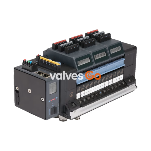
BURKERT 20122700 Type 8652 AirLINE is an electro-pneumatic modular valve island designed to control pneumatic loads and process actuators in automation systems. This assembly features a 16-bank pneumatic configuration mounted on an aluminium AirLINE Quick baseplate, integrating brass push-in fittings, 32 digital inputs across four electronic input modules, and an Industrial EtherNet communication gateway supporting multiple industrial Ethernet protocols.
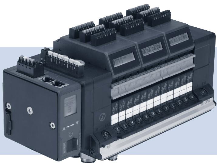
The valve island is factory-populated with 16 pneumatic valve positions. Positions 1 through 14 contain 5/2-way monostable valves in circuit function H (CF-H). Positions 15 and 16 contain 3/2-way monostable valves in circuit function C (CF-C). The pneumatic base incorporates integrated check valves in exhaust channels 3 (R) and 5 (S), as well as pneumatic HotSwap capability in supply port 1 (P), allowing valve replacement under supply pressure.
| Position | Circuit Function | Description |
|---|---|---|
| Slot 1 to Slot 14 | CF-H | 5/2-way monostable pneumatic valve |
| Slot 15 to Slot 16 | CF-C | 3/2-way monostable pneumatic valve |
Process connections are executed in brass with push-in dimensions optimized for industrial automation headers:
| Connection | Dimension | Material | Additional Detail |
|---|---|---|---|
| Supply Connection | D10 | Brass | Primary supply 1 (P) |
| Working Ports | D6 | Brass | Working ports 2 and 4 |
| Baseplate Interface | AirLINE Quick | Aluminium | Control cabinet mounting plate |
| Auxiliary Pilot Air | Internal | — | Sourced from primary air feed |
| Additional Supply Left | Threaded | — | Threaded connections G 1/4" and M7 |
| Additional Supply Middle | None | — | 0 PCE intermediate feed quantity |
| Additional Supply Right | None | — | Without additional feed |
Nominal working pressure ranges from -1.00 bar to 10.00 bar, with required pilot supply pressure between 3.00 bar and 10.00 bar. Permissible operating and ambient temperatures span from -10 °C to +55 °C.
| Operational Parameter | Specified Value |
|---|---|
| Nominal Operating Pressure | -1.00 bar to 10.00 bar |
| Pilot Air Pressure | 3.00 bar to 10.00 bar |
| Medium Temperature | -10 °C to +55 °C |
| Ambient Operating Temperature | -10 °C to +55 °C |
| Nominal Electrical Supply | 24 V DC (±10%) |
| Nominal Supply Current | 3 A (typical rating plate baseline) |
| Degree of Ingress Protection | IP20 (with mating connectors plugged) |
| Pilot Valve Element | Type 6164 (piloting Type 6534 directional valves) |
| Maximum Permissible Valve Slice Functions | 48 functions |
Digital automation interfacing is handled by a modular fieldbus gateway with dual RJ45 hardware ports. The multi-protocol Industrial EtherNet interface supports:
The electronic architecture includes four digital input modules, providing a total of 32 digital input channels (DI) directly on the island assembly for field sensor feedback.
Each Type 8652 valve island carries a primary rating plate showing fundamental electrical, mechanical, and serial data.
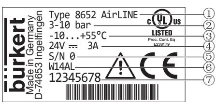
| Position | Description | Example Data on Plate |
|---|---|---|
| 1 | Device Type | Type 8652 AirLINE |
| 2 | Pressure Range | 3–10 bar |
| 3 | Ambient Temperature Range | -10 to +55 °C |
| 4 | Nominal Voltage / Current Consumption | 24 V DC / 3 A |
| 5 | Serial Number | S/N 0 |
| 6 | Manufacturing Code | W14AL |
| 7 | Order Article Number | 20122700 (Example: 12345678) |
When supplied for potentially explosive atmospheres under option codes PX68 or PU17, the Type 8652 platform carries certification for Group II Category 3G and 3D equipment under ATEX Directive 2014/34/EU and the IECEx scheme:
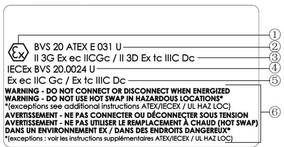
| Marking Element | Code PX68 Marking | Code PU17 Marking |
|---|---|---|
| ATEX Certificate | BVS 20 ATEX E 031 U | BVS 20 ATEX E 031 U |
| IECEx Certificate | IECEx BVS 20.0024 U | IECEx BVS 20.0024 U |
| ATEX Gas / Dust Marking | II 3G Ex ec IIC Gc / II 3D Ex tc IIIC Dc | II 3G Ex ec IIC Gc / II 3D Ex tc IIIC Dc |
| IECEx Gas / Dust Marking | Ex ec IIC Gc / Ex tc IIIC Dc | Ex ec IIC Gc / Ex tc IIIC Dc |
| US / Canada Zone Marking (Gas) | — | Cl I, ZN 2, AEx ec IIC Gc / Ex ec IIC Gc U |
| US / Canada Zone Marking (Dust) | — | Cl II ZN 22, AEx tc IIIC Dc / Ex tc IIIC Dc U |
| US / Canada Division Marking | — | Cl I, Div 2, Gr A, B, C, D / Cl II, III, Div 2, Gr F, G |
| CCC Certification | GB/T 3836-2021 (SITIIAS) | GB/T 3836-2021 (SITIIAS) |
Installation and servicing in hazardous areas must satisfy the following constraints according to EN/IEC 60079-0, EN/IEC 60079-7, and EN/IEC 60079-31:
Hazardous Area Connection and HotSwap Rules
Electrical terminal connections for 24 V power supply, SIA safety shut-off, EVS valve voltage shut-off, and digital inputs must only be plugged or unplugged while de-energized. Pneumatic HotSwap valve removal or insertion is prohibited in hazardous atmospheres unless the environment has been verified as non-explosive using approved test equipment.
Electrostatic and Maintenance Guidance
Electrostatic charge accumulation must be prevented. Clean plastic surfaces and markings only with a damp or antistatic cloth. If cabinet installation obscures the secondary warning marking, affix the included supplemental label: "WARNING DO NOT CONNECT OR DISCONNECT WHEN ENERGIZED" in a clearly visible location.
Explore similar products in our catalog


