

PN16

Burkert 20126827 Type 8652 AirLINE valve island features 24 valve slots with 48 CF-C 3/2-way functions, 48 digital inputs, stainless steel AirLINE Quick base, and multi-protocol Industrial Ethernet.
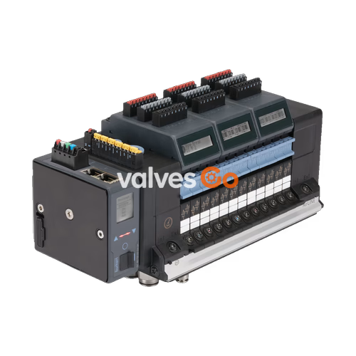
BURKERT Type 8652 (article 20126827) is a high-density 24-bank AirLINE pneumatic valve island configured for process automation environments. This assembly integrates 24 valve slots, each populated with a dual 3/2-way normally closed solenoid valve (Circuit Function C), providing 48 independently actuated pilot functions within an 11 mm per station slice form factor. The unit incorporates 48 digital inputs distributed across six 8DI electronic modules, enabling direct feedback monitoring from process valves and limit switches without separate remote I/O blocks.
Pneumatic process interfacing is executed through a stainless steel 1.4301 AirLINE Quick adapter plate, featuring push-in connectors sized at D10 mm for main compressed air supply and D6 mm for working ports, combined with an intermediate feed module installed between stations. High-level fieldbus control is handled by an integrated multi-protocol Industrial Ethernet gateway supporting PROFINET IO, EtherNet/IP, Modbus TCP, EtherCAT, and CC-Link IE Field Basic over dual RJ45 ports.

| Technical Parameter | Specification Value |
|---|---|
| Type | 8652 AirLINE |
| Article Number | 20126827 |
| Total Valve Slots | 24 slots (11 mm station width) |
| Valve Configuration | Slots 1 to 24: 2x 3/2-way CF-C (normally closed) |
| Total Actuated Valve Channels | 48 channels |
| Digital Inputs | 48 DI (6 modules x 8 DI channels) |
| Base Plate System | AirLINE Quick stainless steel 1.4301 adapter plate |
| Main Supply Connection (1/P) | D10 mm push-in connector, stainless steel 1.4401 |
| Working Ports (2/A, 4/B) | D6 mm push-in connector, stainless steel 1.4401 |
| Intermediate Supply Modules | 1 PCE (middle and right D6/D10 push-in, left blank) |
| Auxiliary Pilot Air | Internal supply |
| Operating Pressure Range | Vacuum to 10 bar (-1.00 bar to 10.00 bar) |
| Auxiliary Pilot Pressure | 3 bar to 10 bar |
| Nominal Air Flow Rate QNn | 310 l/min reference (270 l/min per 2x 3/2-way CF-C valve) |
| Operating Voltage | 24 V DC (±10%, residual ripple 1 Vss) |
| Nominal Power per Valve | 0.7 W initial (0.175 W after electronic power reduction) |
| Nominal Current per Valve | 29 mA initial (10 mA after holding current reduction) |
| Electrical Protection Class | Class III according to DIN EN 61140, VDE 0140 |
| Operating Medium | Oil-free or lubricated dry compressed air, neutral gases |
| Compressed Air Quality | ISO 8573-1:2010, Class 7.4.4 (5 μm filtration recommended) |
| Ambient & Medium Temperature | -10 °C to +55 °C |
| Storage Temperature | -20 °C to +60 °C |
| Enclosure Rating | IP20 naked; IP65 in closed cabinet with AirLINE Quick |
| Type Rating (NEMA 250) | Type 4X in closed enclosures (with stainless steel plate) |
AirLINE Quick enables direct mechanical mounting into the control cabinet floor or wall cutout. By seating the pneumatic bulkheads outside the enclosure, the system eliminates cabinet-internal tubing lines and reduces cabinet volume requirements.
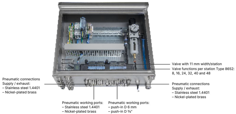
| Property | Detail |
|---|---|
| Adapter Plate Material | Stainless steel 1.4301 |
| Push-in Connector Material | Stainless steel 1.4401 |
| Pneumatic Supply / Exhaust Ports | Push-in D10 mm, G 3/8" |
| Pneumatic Working Ports | Push-in D6 mm, G 1/4" |
| Supported Valve Functions | 8, 16, 24, 32, 40, and 48 |
| Installation Position | Control cabinet bottom floor or cabinet side wall |
Installation Advantage
AirLINE Quick provides ingress protection to IP65 / NEMA 4X at the enclosure interface while ensuring all pneumatic exhaust and working ports remain accessible from the cabinet exterior.
Article 20126827 is populated with dual 3/2-way normally closed solenoid valves across all 24 slots. Each physical slice contains two servo-controlled valves operated by miniature Type 6164 pilot operators.
| Circuit Function | Nominal Diameter | QNn Air Flow | Pressure Range | Opening Time | Closing Time | Voltage | Order Article No. |
|---|---|---|---|---|---|---|---|
| CF C (2x 3/2-way NC, Standard) | 4 mm | 270 l/min | Vac. to 10 bar | 15 ms | 15 ms | 24 V DC | 301374 (Set 296031) |
| CF C (Single 3/2-way NC) | 4 mm | 270 l/min | Vac. to 10 bar | 15 ms | 15 ms | 24 V DC | 20102334 (Set 20088974) |
| CF D (2x 3/2-way NO) | 4 mm | 310 l/min | Vac. to 10 bar | 15 ms | 15 ms | 24 V DC | 301375 (Set 296032) |
| CF H (5/2-way monostable) | 4 mm | 290 l/min | Vac. to 10 bar | 20 ms | 25 ms | 24 V DC | 301376 (Set 296033) |
| CF Z (5/2-way bistable impulse) | 4 mm | 290 l/min | Vac. to 10 bar | 20 ms | 25 ms | 24 V DC | 301377 (Set 296034) |
| CF L (5/3-way mid-position closed) | 4 mm | 275 l/min | Vac. to 10 bar | 15 ms | 15 ms | 24 V DC | 301380 (Set 296036) |
| CF M (5/3-way mid-position ventilated) | 4 mm | 300 l/min | Vac. to 10 bar | 20 ms | 20 ms | 24 V DC | 301379 (Set 296035) |
| CF N (5/3-way mid-position exhausted) | 4 mm | 300 l/min | Vac. to 10 bar | 20 ms | 20 ms | 24 V DC | 301381 (Set 296039) |
| CF C SIA (Safety Shut-Off Variant) | 4 mm | 270 l/min | Vac. to 10 bar | 15 ms | 15 ms | 24 V DC | 338802 (Set 336443) |
| Dummy Valve Plate | — | — | — | — | — | — | 335779 (Set 327614) |
The 48 digital inputs on article 20126827 are arranged into six 8DI electronic modules. These supply 24 V DC power directly to external sensors with current limited to 30 mA per input channel.
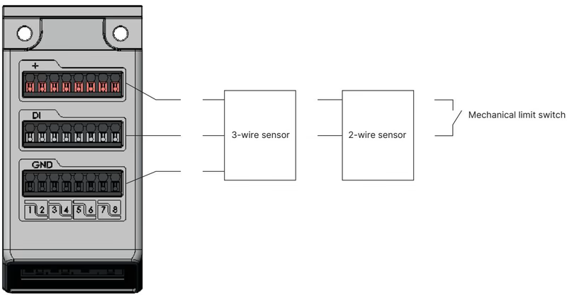
| Technical Attribute | Specification Parameter |
|---|---|
| Module Designation | 8DI Module (Article 384872) |
| Compatible Sensors | 2-wire proximity sensors, 3-wire PNP sensors, mechanical limit switches |
| Switching Thresholds | V_OFF = 0 to 5 V; V_ON = 10 to 30 V |
| Input Current at V_ON | Max. 5.7 mA per channel (typical at 24 V DC) |
| Input Impedance | > 4 kΩ |
| Diagnostic Capabilities | Open-circuit detection (2-wire), short-circuit detection (3-wire) |
| Galvanic Isolation | No galvanic isolation; shared common reference potential |
| Maximum Cable Length | < 30 m |
| Terminal Wire Cross-Section | Pluggable screw terminal, 0.14 mm² to 1.5 mm² (AWG 28–16) |
| Process Signal / Status | 3-Wire Sensor | 2-Wire Sensor | Mechanical Limit Switch |
|---|---|---|---|
| Sensor Actuated | Yes | Yes | Yes |
| Sensor Not Actuated | Yes | Yes | Yes |
| Short-Circuit Fault | Detected | — | — |
| Wire-Break Fault | — | Detected | — |
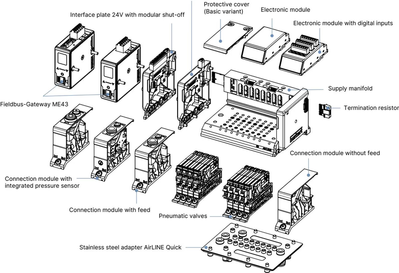
Article 20126827 separates power feeds for communication logic and pneumatic valve coils, enabling independent emergency shutdowns.
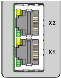
| RJ45 Pin | Industrial Ethernet Signal Assignment |
|---|---|
| Pin 1 | TX+ (Transmit Data +) |
| Pin 2 | TX- (Transmit Data -) |
| Pin 3 | RX+ (Receive Data +) |
| Pin 4 | Not connected (N.C.) |
| Pin 5 | Not connected (N.C.) |
| Pin 6 | RX- (Receive Data -) |
| Pin 7 | Not connected (N.C.) |
| Pin 8 | Not connected (N.C.) |
For the 24-valve bank version with intermediate supply, dimensional planning must accommodate mounting pitch and hot swap clearance.
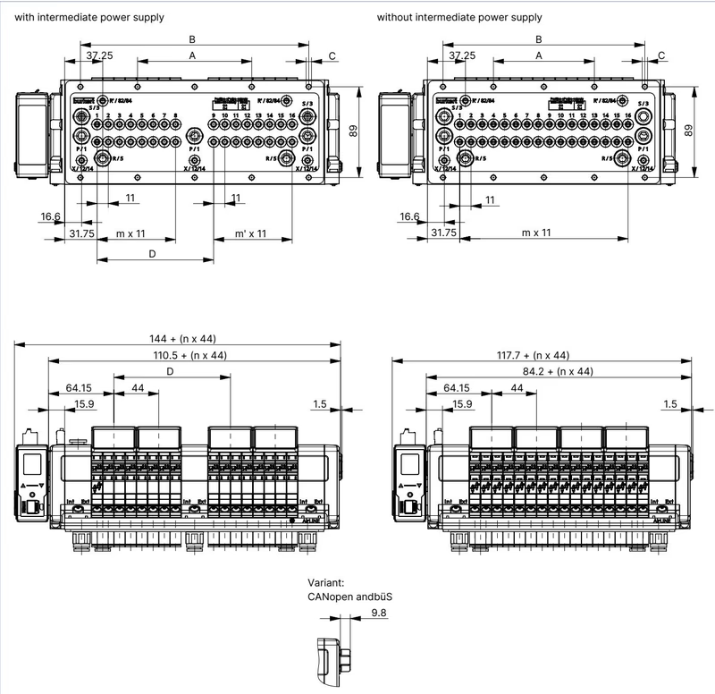
| Variant Configuration | A [mm] | B [mm] | C [Holes] | D [mm] | m [Slices] | m' [Slices] | n [Slots] |
|---|---|---|---|---|---|---|---|
| 24-fold with Intermediate Supply | 156 | 312 | 10 x M5 | 158.3 | 11 | 11 | 6 |
| 20-fold with Intermediate Supply | 134 | 268 | 10 x M5 | 158.3 | 11 | 7 | 5 |
| 16-fold with Intermediate Supply | 112 | 224 | 10 x M5 | 114.3 | 7 | 7 | 4 |
| 24-fold without Intermediate Supply | 143 | 286 | 10 x M5 | — | 23 | — | 6 |
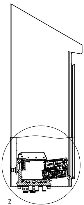
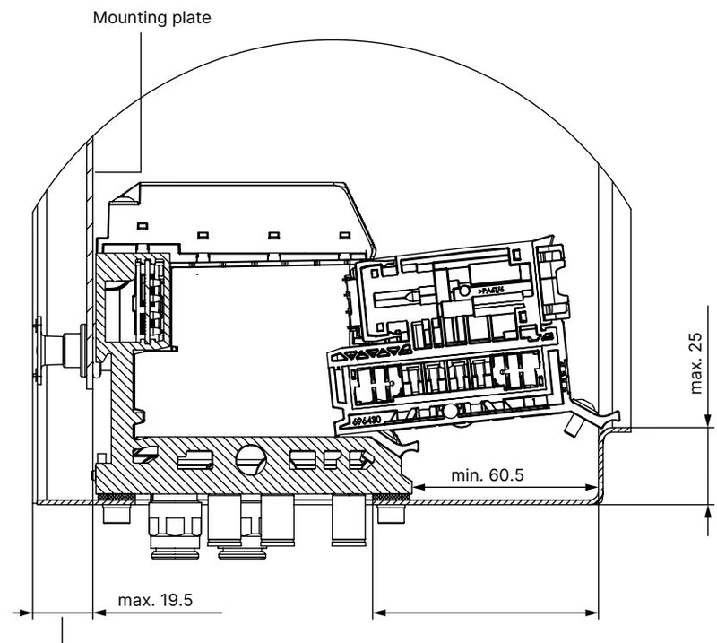
To ensure proper valve insertion and extraction under maintenance, maintain the minimum specified clearance between the valve slice front edge and the cabinet door framing. DIN rail mounting is supported via EN 50022 35 x 7.5 or 35 x 15 rails.
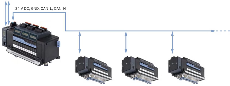
Type 8652 operates as a communication hub within the Bürkert EDIP platform. When equipped with the Industrial Ethernet module, the valve terminal functions as an Ethernet master while orchestrating downstream büS slave valve blocks over its backplane.
Special Conditions for Safe Use in Hazardous Locations
| Accessory Description | Quantity | Order Article No. |
|---|---|---|
| Screw Set M5 x 10 A2 DIN 6912 (Fastening to Cabinet Base) | 10 pcs | 308661 |
| Height Adapter for 24-fold Base with Intermediate Feed | 1 pc | 754964 |
| Retaining Plate (External Cabinet Frame) for 24-fold with Feed | 1 pc | 60005570 |
| Blind Plate for 24-fold Cutout with Intermediate Feed | 1 pc | 754969 |
| 5-Pin Spring-Loaded Terminal (Logic and Display Power) | 1 pc | 920180 |
| 2-Pin Spring-Loaded Terminal (Valve Auxiliary Power) | 1 pc | 920442 |
| USB büS Interface Set 1 (Type 8923 with Communicator Stick) | 1 set | 772426 |
| büS Terminating Resistor 120 Ω (M12 Plug) | 1 pc | 772424 |
Explore similar products in our catalog


