

PN16

BURKERT 20129632 (Type 8652) is a 16-station AirLINE Quick pneumatic valve island with Industrial Ethernet, 32 digital inputs, D10 supply, D6 brass working ports, pneumatic hot swap, and integrated check valves.
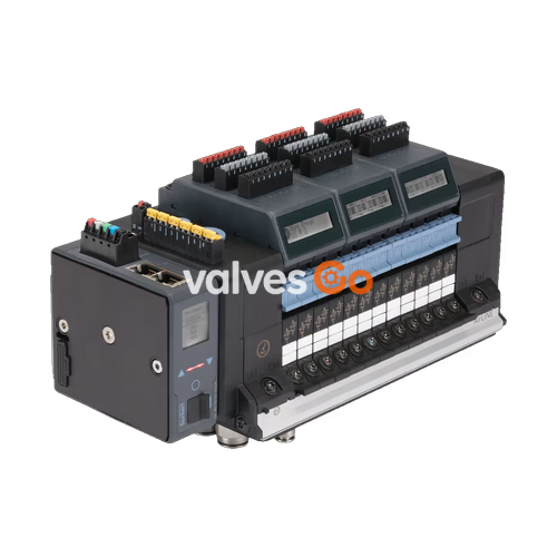
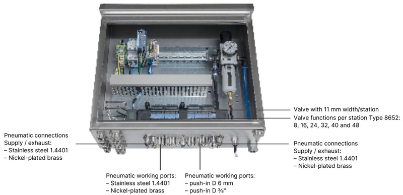
BURKERT 20129632 (Type 8652) is an electropneumatic AirLINE valve island configured with 16 valve slots, designed specifically for process automation environments. Every valve slot from position 1 through 16 is populated with a 5/2-way monostable Type 6534 solenoid valve (circuit function H). The unit integrates an AirLINE Quick adapter plate manufactured from anodised aluminium, enabling direct installation through the floor or wall of a control cabinet. All pneumatic connection lines pass through the cabinet wall, isolating the internal electronic modules and fieldbus interface from process lines while achieving IP65 enclosure integrity when mounted in an appropriate cabinet.
Diagnostic information and active statuses are visualised directly on the built-in LC display in plain text and symbols. These status messages are mirrored over the industrial communication link directly to the supervisory PLC. Process reliability features include integrated check valves in exhaust ducts 3 (R) and 5 (S) to suppress pressure peaks, as well as a pneumatic HotSwap mechanism in supply port 1 (P) that permits replacement of individual valve slices while the manifold remains pressurized.
| Parameter | Value |
|---|---|
| Number of Valve Stations | 16 PCE |
| Station Pitch / Width per Station | 11 mm |
| Valve Configuration (Positions 1 to 16) | 5/2-way monostable, circuit function H (CF-H) |
| Pilot Valve Type | Type 6164 pilot control elements |
| Body Material | Polyamide (PA) |
| Seal Materials | NBR and PUR |
| AirLINE Quick Adapter Material | Anodised aluminium |
| Supply Port 1 (P) Connection | Push-in D10 mm (brass) |
| Working Ports 2 (B) and 4 (A) | Push-in D6 mm (brass) |
| Auxiliary Supply Port (Left) | G 1/4" and M7 threaded ports |
| Nominal Operating Pressure Range | -1.00 bar to 10.00 bar (Vacuum to 10 bar) |
| Auxiliary Pilot Air Pressure | 3.00 bar to 10.00 bar (internal feed) |
| Nominal Flow Rate QNn (Air) | 290 l/min (at +20 °C, 6 bar inlet, 1 bar Δp) |
| HotSwap Flow Impact | Approx. 3% flow reduction |
| Operating Voltage | 24 V DC (±10%, residual ripple 1 Vss) |
| Power Consumption per Valve | 0.7 W nominal (0.175 W after power reduction) |
| Nominal Current per Valve | 29 mA (10 mA after power reduction) |
| Operating Mode | Continuous operation (100% ED) |
| Total Digital Inputs | 32 DI (4 modules x 8 DI) |
| Ingress Protection | IP20 standalone; IP65 inside closed cabinet via AirLINE Quick |
| Medium and Ambient Operating Temperature | -10 °C to +55 °C |
| Storage Temperature | -20 °C to +60 °C |
| Medium Specification | Lubricated or oil-free dry compressed air, neutral gases (ISO 8573-1:2010, Class 7.4.4, 5 μm filter recommended) |
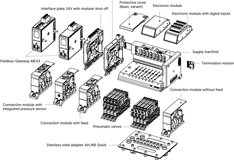
The AirLINE Quick system minimizes wiring and tubing runs inside electrical enclosures. Instead of routing 32 working pneumatic lines and main supply headers within the cabinet interior, the anodised aluminium adapter plate is secured to a cutout in the cabinet floor or side panel. The pneumatic connections (D10 mm push-in for supply, D6 mm push-in for working ports) seat externally on the adapter block, while the valve island mechanics and electrical interface remain clean and dry inside.
AirLINE Quick Advantages
BURKERT 20129632 incorporates an integrated fieldbus gateway module supporting Industrial Ethernet multi-protocol operation. The interface supports PROFINET IO, EtherNet/IP, Modbus TCP, EtherCAT, and CC-Link IE Field Basic via two RJ45 female ports labeled X1 and X2.
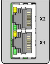
| Pin | Signal Assignment |
|---|---|
| 1 | TX+ |
| 2 | TX- |
| 3 | RX+ |
| 4 | Not connected (N.C.) |
| 5 | Not connected (N.C.) |
| 6 | RX- |
| 7 | Not connected (N.C.) |
| 8 | Not connected (N.C.) |
Power supply connections for the electronic logic/fieldbus gateway and the solenoid coil circuits are physically separated to support independent emergency stop routing:
| Connector | Pin | Wire Colour | Assignment |
|---|---|---|---|
| 5-pin spring terminal (Logic & büS) | 1 | Red | +24 V DC (Communication and display) |
| 2 | White | CAN_H (büS interface) | |
| 3 | Green | Shielding | |
| 4 | Blue | CAN_L (büS interface) | |
| 5 | Black | 0 V DC (GND) | |
| 2-pin spring terminal (Valve Power) | 1 | Red | AUX +24 V DC (Pneumatic valve supply) |
| 2 | Black | 0 V DC (GND) |
BURKERT 20129632 includes four 8DI electronic modules, providing a total of 32 digital input channels to read back end-position sensors or external switches directly over the network bus.
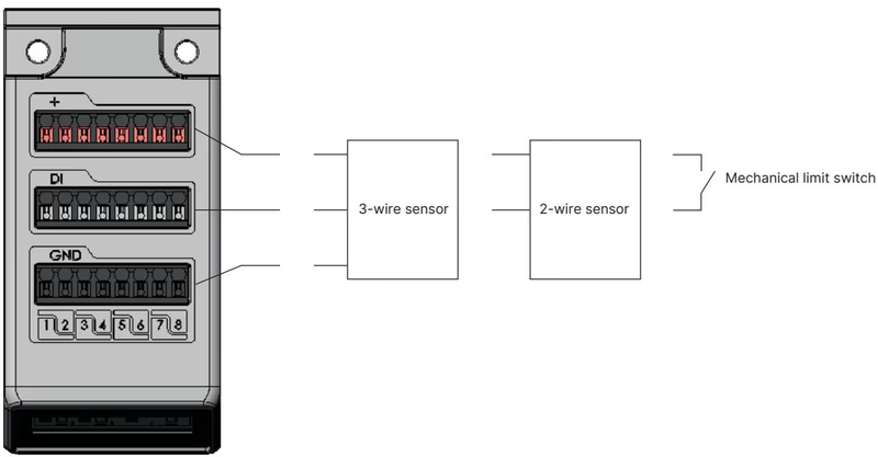
| Parameter | Specification |
|---|---|
| Number of Channels | 32 inputs (4 modules x 8 channels) |
| Supported Sensor Types | 2-wire sensors, 3-wire sensors, mechanical limit switches |
| Switching Thresholds | V_OFF = 0 to 5 V DC; V_ON = 10 to 30 V DC |
| Input Current at V_ON | Max. 5.7 mA per channel (typical 24 V DC) |
| Input Impedance | > 4 kΩ |
| Sensor Supply | 24 V DC from module, current limited to 30 mA per input |
| Galvanic Isolation | No (common reference potential across all channels) |
| Maximum Cable Length | < 30 m (conductor cross-section ≤ 1.5 mm²) |
| Diagnostics Available | Wire-break detection (2-wire sensors); short-circuit detection (3-wire sensors) |
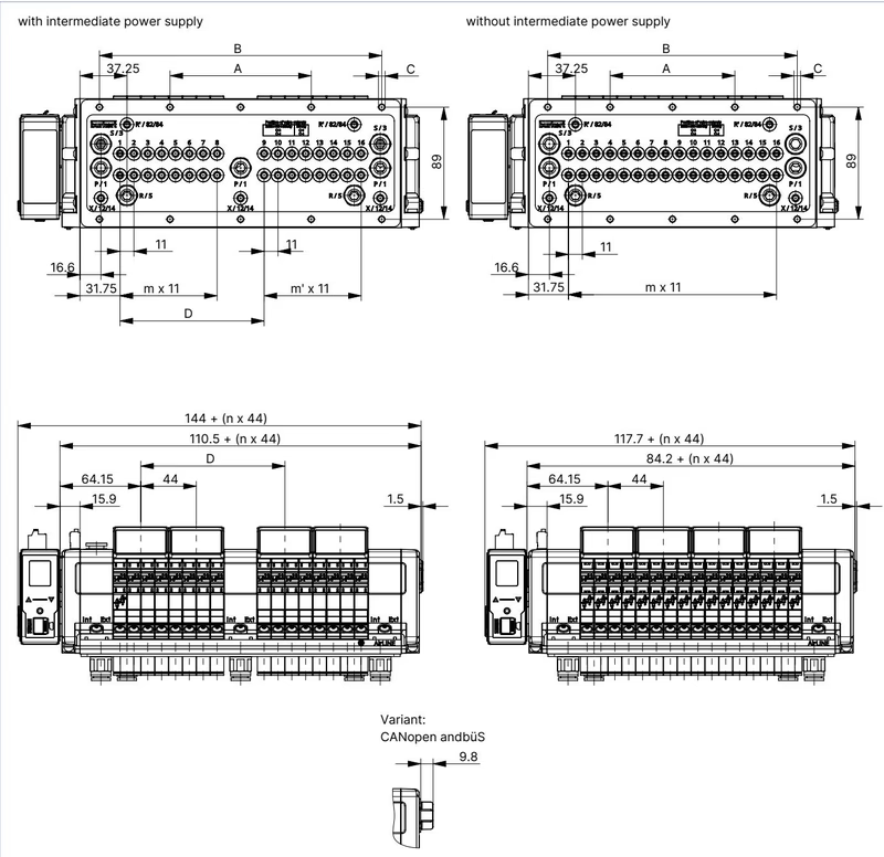
For the 16-valve variant without intermediate supply modules (standard configuration of 20129632):
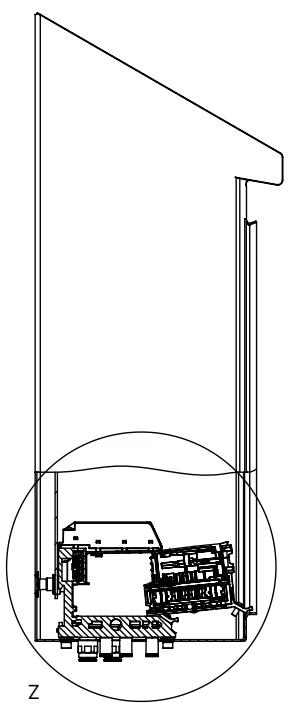
Installation Clearance for Hot Swap
When mounting inside a control cabinet, maintain the required clearance between the front edge of the valve island and the cabinet door/frame. This allows individual Type 6534 valve slices to tilt forward and unseat cleanly from the pneumatic base during live maintenance without mechanical interference.
Type 8652 is certified for hazardous environment use under ATEX and IECEx Zone 2/22 as well as North American Class I, Division 2 / Zone 2 standards when enclosed properly:
Hazardous Area Operational Restrictions
| Component Description | Details / Application | Article No. |
|---|---|---|
| Replacement Valve Type 6534 CF-H | 5/2-way monostable solenoid valve, 24 V DC, 290 l/min (Ref. 296033) | 301376 |
| Valve Blanking Plate | Seals unused positions when a valve slice is removed (Ref. 327614) | 335779 |
| 8DI Electronic Module | Replacement module with 8 digital inputs for Type 8652 | 384872 |
| 5-Pin Spring-Loaded Terminal | Pluggable connector for logic power and büS communication | 920180 |
| 2-Pin Spring-Loaded Terminal | Pluggable connector for pneumatic valve power supply (AUX 24 V) | 920442 |
| AirLINE Quick Screw Set | 10x M5 x 10 A2 DIN 6912 fasteners for cabinet base mounting | 308661 |
| Height Adapter (16-fold without feed) | Mechanical height compensation plate for 16-valve baseplate | 60041928 |
| Retaining Plate (16-fold without feed) | Exterior cabinet mounting bracket for 16-valve baseplate | 60005880 |
| Blind Plate (16-fold without feed) | Blanking cover plate for cabinet cutout | 60041929 |
Explore similar products in our catalog


