

PN16

BURKERT 20135392 Type 8652 AirLINE 12-slot valve island integrates Industrial Ethernet, AirLINE Quick aluminium adapter plate, HotSwap in port P, and 12th slot SIA safety shut-off.
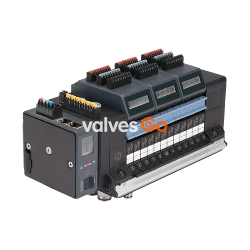
BURKERT 20135392 Type 8652 AirLINE is a preconfigured 12-slot pneumatic valve island developed specifically for process automation installations. Equipped with an integrated ME43 Industrial Ethernet communication interface supporting PROFINET IO, EtherNet/IP, Modbus TCP, EtherCAT, and CC-Link IE Field Basic over dual RJ45 ports, the terminal provides direct process control and comprehensive diagnostics on an LC display as clear text and symbols. Diagnostics are also transmitted cyclically to the higher-level PLC to accelerate commissioning and fault tracking.

The 20135392 configuration is assembled on an AirLINE Quick anodised aluminium baseplate for direct mounting to the floor or wall of a control cabinet. It features brass push-in connectors (D10 supply port, D6 working ports), internal auxiliary pilot air supply, and an auxiliary left threaded feed (G 1/4" and M7). The valve bank includes 11 standard stations with 2x 3/2-way normally closed valves and a 12th station equipped with a Type 6534 SIA safety shut-off valve with potential-free shutdown contacts, controlling up to 24 independent pneumatic paths.
Model 20135392 provides a factory-assembled pneumatic and electronic configuration tailored for high-density cabinet installations:
| Specification Parameter | Value / Configuration |
|---|---|
| Article Number | 20135392 |
| Terminal Type | 8652 AirLINE |
| Total Valve Slots | 12 slots (PCE) |
| Valve Positions 1 to 11 | 2x 3/2-way Circuit Function C (normally closed) |
| Valve Position 12 | 2x 3/2-way Circuit Function C SIA (safety shut-off variant) |
| Fieldbus Communication | Industrial Ethernet (PROFINET IO, EtherNet/IP, Modbus TCP, EtherCAT, CC-Link IE Field Basic) |
| Physical Interface | Dual RJ45 ports (X1 and X2) |
| Supply Connection (P) | Push-in D10 mm, Brass |
| Working Ports (A, B) | Push-in D6 mm, Brass |
| Baseplate Interface | AirLINE Quick, Anodised Aluminium |
| Pilot Air Configuration | Internal auxiliary pilot air |
| Left Additional Supply | Threaded ports G 1/4" and M7 |
| Right / Middle Supply | Without additional feed (0 intermediate supply modules) |
| Digital Input Modules | 0 DI (none fitted) |
| Exhaust Check Valves | Integrated check valves in ports 3 (R) and 5 (S) |
| HotSwap Function | Integrated pneumatic HotSwap in supply port 1 (P) |
Type 8652 operates continuously (100% duty cycle) across standard compressed air networks, conforming to ISO 8573-1:2010 Class 7.4.4 air quality.
| Feature Group | Parameter | Specification Value |
|---|---|---|
| Materials | Body | Polyamide (PA) |
| Seals | NBR and PUR | |
| Width per Station | 11 mm | |
| Pneumatic Data | Operating Pressure Range | -1.00 bar to 10.00 bar (Vacuum to 10 bar) |
| Auxiliary Pilot Air Pressure | 3 bar to 10 bar | |
| Nominal Flow Rate QNn (Air) | 270 l/min (2x 3/2-way CF-C, measured at +20 °C, 6 bar inlet, 1 bar Δp) | |
| HotSwap Flow Impact | Flow reduced by approx. 3% | |
| Switching Times (ISO 12238) | Opening: 15 ms; Closing: 15 ms | |
| Manual Override | Latching / spring return (standard valves) | |
| Electrical Data | Operating Voltage | 24 V DC (±10%, residual ripple 1 Vss) |
| Nominal Power per Valve | 0.7 W (drops to 0.175 W after electronic power reduction) | |
| Nominal Current per Valve | 29 mA (drops to 10 mA after power reduction) | |
| Protection Class | Class III according to DIN EN 61140, VDE 0140 | |
| Environment | Ambient Temperature Range | -10 °C to +55 °C |
| Storage Temperature Range | -20 °C to +60 °C | |
| Operating Medium | Lubricated or oil-free compressed dry air, neutral gases (5 µm filter recommended) | |
| Degree of Protection | IP20 (standalone); IP65 in closed cabinet with AirLINE Quick |
The AirLINE Quick system allows the valve terminal to mount directly onto the floor or wall of a control cabinet, leading pneumatic tubing straight through the enclosure cutout. This layout eliminates intermediate bulkheads and internal tubing runs, allowing significantly smaller cabinet enclosures.
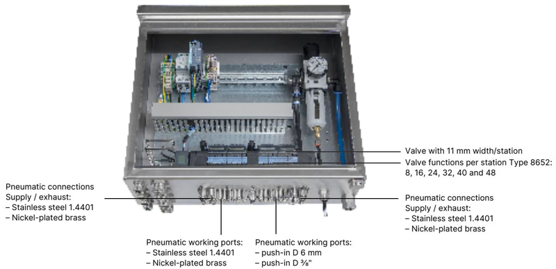
| Component / Feature | Specification Details |
|---|---|
| Adapter Plate Material | Anodised aluminium (also available in stainless steel 1.4301) |
| Pneumatic Fitting Material | Nickel-plated brass (stainless steel 1.4401 optional) |
| Pneumatic Supply / Exhaust Ports | Push-in connector D10 mm (3/8") |
| Pneumatic Working Ports | Push-in connector D6 mm (1/4") |
| Mounting Position | Control cabinet floor or cabinet wall |
For a 12-slot valve terminal, external dimensions follow standardized Burkert pitch dimensions. Mounting is supported directly onto the cabinet wall, cabinet floor cutout, or standard DIN rails EN 50022 (35 x 7.5 mm or 35 x 15 mm).
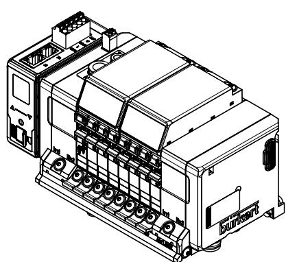
| Terminal Size | Dimension A (mm) | Dimension B (mm) | Mounting Screws C | Pitch Index m | Spacing Index n |
|---|---|---|---|---|---|
| 4-fold | 66 | — | 4 x M5 | 3 | 1 |
| 8-fold | 35 | 111 | 8 x M5 | 7 | 2 |
| 12-fold (20135392) | 77 | 154 | 10 x M5 | 11 | 3 |
The valve terminal provides galvanic and electrical separation between the communication electronics and the pneumatic coil power circuits. Both power feeds must be supplied independently.
Power supply to the display and fieldbus communication module is wired through a 5-pin spring-loaded terminal block (wire cross-section ≤ 1.5 mm²):
| Pin Position | Terminal Colour | Function / Assignment |
|---|---|---|
| 1 | Red | 24 V DC |
| 2 | White | CAN_H (büS connection) |
| 3 | Green | Shielding |
| 4 | Blue | CAN_L (büS connection) |
| 5 | Black | 0 V DC (GND) |
Pneumatic valve coils receive power via a dedicated 2-pin spring-loaded terminal on the interface plate:
| Terminal Clip | Terminal Colour | Function / Assignment |
|---|---|---|
| 1 | Red | AUX 24 V DC |
| 2 | Black | 0 V DC (GND) |
Dual RJ45 sockets support daisy-chain topology and ring redundancy protocols across Industrial Ethernet standards:
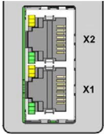
| RJ45 Pin | Signal Assignment | Description |
|---|---|---|
| 1 | TX+ | Transmit Data + |
| 2 | TX- | Transmit Data - |
| 3 | RX+ | Receive Data + |
| 4 | N.C. | Not connected |
| 5 | N.C. | Not connected |
| 6 | RX- | Receive Data - |
| 7 | N.C. | Not connected |
| 8 | N.C. | Not connected |
Type 8652 includes pneumatic HotSwap in supply port 1 (P), allowing individual pilot valves to be replaced under full line pressure without shutting down adjacent actuators or bleeding the main air line. Check valves built into exhaust channels 3 (R) and 5 (S) prevent reverse pressure surges from inadvertently moving single-acting cylinders.
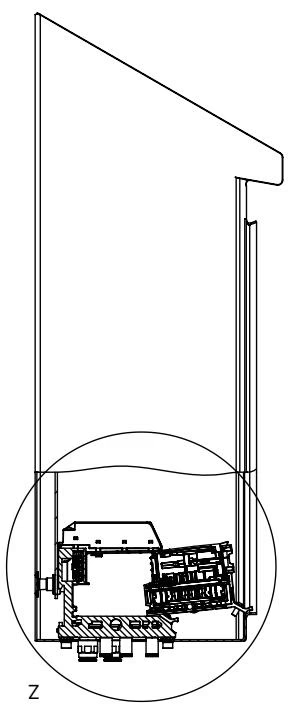
HotSwap Maintenance Distance
To safely insert and release individual valve slices using the HotSwap mechanism, adhere to the minimum spacing between the terminal body and the front edge or doors of the control cabinet as defined in the Type 8652 operating instructions.
Position 12 on model 20135392 is fitted with a Type 6534 SIA variant valve. While slots 1 to 11 use standard 2x 3/2-way normally closed valves with manual overrides, the SIA variant features dedicated electrical terminal connections to interrupt the coil circuit externally via emergency contacts or safety relays, completely bypassing bus communication.
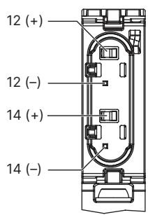
| Feature | SIA Safety Shutdown Specification |
|---|---|
| Terminal Type | Pluggable screw-type terminal, 2-pin, mechanically coded |
| Conductor Cross-Section | 0.14 mm² to 1.5 mm² (AWG 28–16), rigid or flexible |
| Contact Switching Capacity | 0.5 A at 24 V DC |
| Manual Override | None (manual operation omitted on SIA versions) |
| Delivery Condition | Fitted with removable bypass bridge for immediate commissioning |
| External Contact Type | Potential-free contact (mechanical safety switch or safety relay) |
Type 8652 with Industrial Ethernet acts as a fieldbus master gateway that coordinates pneumatic sub-stations across an automation cell. Downstream Bürkert büS valve islands can be integrated into the network topology as slaves.
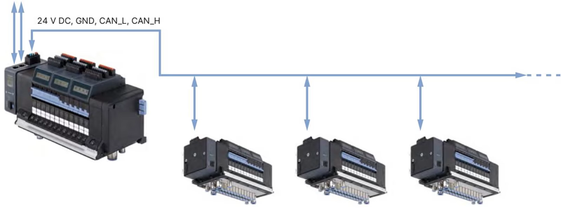
Configuration, parameterization, and diagnostic logging are executed using the Bürkert Communicator software (Type 8920) on the EDIP platform via a PC-linked USB-büS interface adapter.
Individual valve slices, connectors, and mounting hardware can be ordered as replacement units or expansions:
| Circuit Function | Width | Pressure Range | Flow Rate QNn | Voltage | Article No. (incl. screws) |
|---|---|---|---|---|---|
| 2x 3/2-way CF-C Standard (Manual override, NC) | 11 mm | Vac. to 10 bar | 270 l/min | 24 V DC | 301374 (REF 296031) |
| 2x 3/2-way CF-C SIA (External shut-off, NC) | 11 mm | Vac. to 10 bar | 270 l/min | 24 V DC | 338802 (REF 336443) |
| Dummy Valve Plate | 11 mm | — | — | — | 335779 (REF 327614) |
| Component Description | Wiring Details | Article No. |
|---|---|---|
| 5-Pin Spring-Loaded Terminal Block | Communication & display power supply | 920180 |
| 2-Pin Spring-Loaded Terminal Block | Pneumatic valve coil power supply | 920442 |
| ME43 Gateway Module | Industrial Ethernet (PROFINET, EtherNet/IP, Modbus TCP, EtherCAT) | 301799 |
| Accessory Item | Specification / Application | Quantity | Article No. |
|---|---|---|---|
| Fastening Screw Set | M5 x 10 A2 DIN 6912 (fastening to cabinet base) | 10 pcs | 308661 |
| Height Adapter Plate | 12-fold, without intermediate supply | 1 pc | 754961 |
| Retaining Plate | 12-fold, for cabinet exterior mounting | 1 pc | 60005567 |
| Blind Cover Plate | 12-fold, without intermediate supply | 1 pc | 754966 |
When specified for potentially explosive atmospheres under codes PU17 or PX68, Type 8652 conforms to international explosion-protection certifications:
Potentially Explosive Atmosphere Precautions
Terminal blocks for 24 V power, SIA shutdown, and digital inputs must only be connected or disconnected in an unpowered state when an explosive atmosphere is present. Pneumatic HotSwap must not be performed in hazardous locations unless the area is verified to be non-explosive using calibrated test equipment. For Zone 2 (3G) installations, the cabinet enclosure must provide at least IP54 ingress protection; for Zone 22 (3D), at least IP6X is required.
Explore similar products in our catalog


