

PN16

BURKERT 20137550 (Type 8652) is an IP20 4-bank AirLINE valve island featuring D10/D6 stainless steel ports, Industrial Ethernet RJ45, 8 digital inputs, and pneumatic HotSwap.
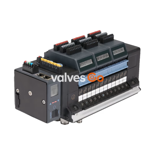
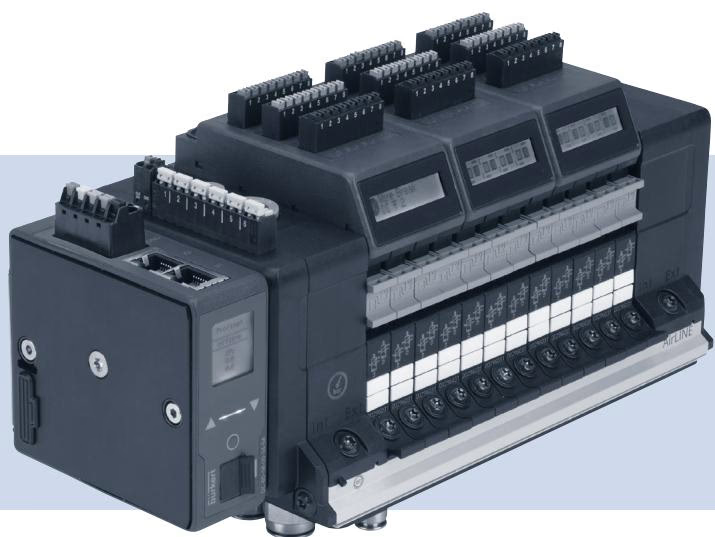
BURKERT 20137550 (Type 8652) is an AirLINE modular valve island configured with 4 valve slots, each populated with a 2x 3/2-way CF-C valve slice. Engineered for control cabinet integration, this specific build incorporates an AirLINE Quick stainless steel interface plate with D10 supply ports and D6 working connections. The system is designed to control pneumatic process actuators in automated plants, providing pilot operation across a nominal pressure span of -1.0 bar to 10.0 bar and a pilot pressure window of 3.0 bar to 10.0 bar.
Communication is executed through an integrated Industrial EtherNet fieldbus module with dual RJ45 Ethernet ports, supporting PROFINET IO, EtherNet/IP, Modbus TCP, EtherCAT, and CC-Link IE Field Basic. An on-board digital input module delivers 8 channels for direct position feedback or sensor acquisition. Process security is maintained by integrated non-return check valves in exhaust ports 3 (R) and 5 (S), alongside pneumatic HotSwap capabilities in supply duct 1 (P) that allow valve replacement under supply pressure.
| Parameter | Value |
|---|---|
| Article Number | 20137550 |
| Valve Island Type | 8652 AirLINE |
| Number of Valve Slots | 4 PCE |
| Valve Positions 1 to 4 | 2x 3/2-way CF-C |
| Supply Port Connection | D10 push-in (Stainless steel) |
| Working Port Connection | D6 push-in (Stainless steel) |
| Interface Plate Material | AirLINE Quick Stainless steel |
| Auxiliary Pilot Air | Internal |
| Additional Supply Connections | Right: G 1/4" and M7; Left: G 1/4" and M7; Middle: None |
| Nominal Pressure ($P_{\text{nom}}$) | -1.0 bar to 10.0 bar |
| Pilot Pressure ($P_{\text{pilot}}$) | 3.0 bar to 10.0 bar |
| Medium Temperature | -10 °C to +55 °C |
| Ambient Operating Temperature | -10 °C to +55 °C |
| Operating Voltage | 24 V DC (±10%) |
| Pilot Valve Element | Type 6164 (actuating Type 6534 pneumatic valves) |
| Digital Inputs | 8 channels (Electrical module 1 with DI) |
| Fieldbus Protocol | Industrial EtherNet (PROFINET IO, EtherNet/IP, Modbus TCP, EtherCAT, CC-Link IE Field Basic) |
| Hardware Ports | RJ45 |
| Integrated Check Valves | Port 3 (R) and Port 5 (S) |
| HotSwap Support | Pneumatic HotSwap in Port 1 (P) |
| Degree of Protection | IP20 (maximum with suitable connection) |
The 20137550 configuration consists of four pneumatic valve slots. Each position is occupied by a 2x 3/2-way CF-C pneumatic valve, driven by Burkert Type 6164 pilot solenoids acting on Type 6534 pneumatic bodies. Auxiliary pilot air is routed internally. Auxiliary supply connections are provided on both the right and left lateral blocks using threaded ports (G 1/4" and M7), while intermediate supply modules are absent (0 PCE).
Non-return check valves integrated into exhaust channels 3 (R) and 5 (S) prevent back-pressure surges from influencing adjacent actuators during exhaust cycles. The supply channel 1 (P) features integrated HotSwap valves, which mechanically seal the pressure channel when a valve slice is unbolted.
HotSwap Operation in Safe Areas
Pneumatic HotSwap allows individual valve slices to be replaced during active pneumatic operation without depressurizing the main air header. When a valve module is unscrewed, the spring-loaded seal in port 1 closes automatically to prevent pressure drop.
The valve island operates from a nominal 24 V DC supply (±10%). Current consumption depends on the active coil count and module complement, with standard baseline nameplates rated up to 3 A. Electrical Module 1 provides 8 digital inputs designed for field sensor feedback, eliminating standalone I/O blocks inside the cabinet.
Network communication is established via the multi-protocol Industrial EtherNet module. Connection is made through standard RJ45 female connectors. Protocol selection covers PROFINET IO, EtherNet/IP, Modbus TCP, EtherCAT, and CC-Link IE Field Basic, allowing direct integration into centralized PLC architectures.
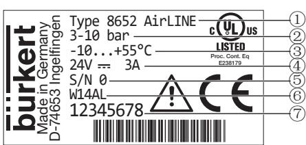
Standard AirLINE Type 8652 units feature a factory data plate detailing essential operating constraints:
| Position | Description | Value Example |
|---|---|---|
| 1 | Device Type | Type 8652 AirLINE |
| 2 | Pressure Range | 3–10 bar |
| 3 | Ambient Temperature Range | -10 °C to +55 °C |
| 4 | Rated Voltage / Current | 24 V DC / 3 A |
| 5 | Serial Number | S/N 0 |
| 6 | Manufacturing Code | W14AL |
| 7 | Order Article Number | 20137550 (illustrated by 12345678 sample) |
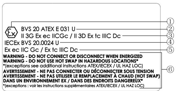
When deployed under hazardous location options (such as code PX68 or PU17), Type 8652 complies with European ATEX Directive 2014/34/EU, IECEx standards, and North American NEC rules for Zone 2 and Zone 22 applications.
| Marking Parameter | Code PX68 Marking | Code PU17 Marking |
|---|---|---|
| ATEX Gas / Dust Marking | II 3G Ex ec IIC Gc / II 3D Ex tc IIIC Dc | II 3G Ex ec IIC Gc / II 3D Ex tc IIIC Dc |
| ATEX Certificate Number | BVS 20 ATEX E 031 U | BVS 20 ATEX E 031 U |
| IECEx Certificate Number | IECEx BVS 20.0024 U | IECEx BVS 20.0024 U |
| IECEx Gas / Dust Marking | Ex ec IIC Gc / Ex tc IIIC Dc | Ex ec IIC Gc / Ex tc IIIC Dc |
| US/CA Class & Zone (Gas) | — | Cl I, ZN 2, AEx ec IIC Gc / Ex ec IIC Gc U |
| US/CA Class & Zone (Dust) | — | Cl II, ZN 22, AEx tc IIIC Dc / Ex tc IIIC Dc U |
| US/CA Divisions | — | Cl I, Div 2, Gr A, B, C, D / Cl II, III, Div 2, Gr F, G |
Electrical Safety in Potentially Explosive Atmospheres
Terminal connections for the 24 V DC power supply, SIA (safety shut-off), EVS (external valve shutdown), and digital inputs must only be connected or disconnected when completely de-energized. Do not connect or disconnect live electrical equipment in an explosive atmosphere.
HotSwap Restrictions in Hazardous Locations
HotSwap functionality is strictly prohibited while an explosive atmosphere is present. Valve modules may only be disconnected or installed via HotSwap if appropriate measuring instruments verify and guarantee that no explosive atmosphere exists throughout the entire duration of the procedure.
Explore similar products in our catalog


