PN16

BURKERT 20138371 Type 8647 is a Revision 2 12-bank electropneumatic valve island for Siemens SIMATIC ET 200SP/SP HA with 12x 2x3/2-way NC valves, 11 mm width, G 1/4 supply, D6 bottom ports, and 1 intermediate feed.
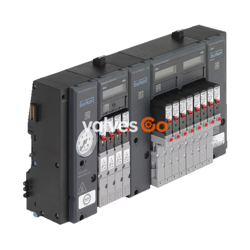
BURKERT 20138371 Type 8647 AirLINE SP is a modular electropneumatic valve island engineered for complete, direct integration into Siemens SIMATIC ET 200SP and SIMATIC ET 200SP HA distributed I/O systems. As an official Siemens Product Partner automation solution, this 11 mm station-width assembly allows pilot solenoid valves to interface directly with the backplane bus of the ET 200SP station, controlling pneumatic process valves, actuators, and cylinders without discrete field wiring between the PLC output cards and valve solenoids.
Article 20138371 is configured as a 12-bank valve terminal belonging to the Revision 2 (REV.2) generation. It contains 12 valve stations equipped exclusively with Type 6524 2x 3/2-way pilot solenoid valves in circuit function C C (both valves monostable, normally closed). This provides 24 independently actuated pneumatic working channels within a compact 12-station footprint. The manifold includes one intermediate pneumatic feed module (PSU-M) positioned along the block to satisfy pneumatic supply volume requirements, G 1/4 primary supply and exhaust connections, and bottom-oriented D6 push-in couplings for all 24 working ports.
| Parameter | Specification |
|---|---|
| Article number | 20138371 |
| Type | 8647 AirLINE SP |
| Generation | Revision 2 (REV.2) |
| Valve station width | 11 mm |
| Number of valve slots | 12 slots (12-bank) |
| Configured valve function | 12x (2x 3/2-way) circuit function C C (normally closed) |
| Total pneumatic control channels | 24 independent channels |
| Operating pressure range | 2.5 bar to 10.0 bar (gauge pressure) |
| Flow rate ($Q_{Nn}$ value air) | 300 l/min (at +20 °C, 6 bar inlet, 1 bar pressure drop) |
| Fluid medium | Compressed dry air (lubricated or unlubricated), neutral gases |
| Compressed air quality | ISO 8573-1:2010, Class 7.4.4 (5 µm filter recommended) |
| Medium temperature range | 0 °C to +50 °C |
| Ambient operating temperature | 0 °C to +55 °C |
| Storage temperature | -20 °C to +60 °C |
| Operating voltage | 24 V DC (±10%), max. residual ripple 2.4 Vss |
| Nominal power consumption | 2x 0.8 W per station (with integrated power reduction) |
| Inrush / holding current per valve | 40 mA inrush (28 mA holding current after 120 ms) |
| Working ports 2 (A) and 4 (B) | D6 push-in couplings, bottom oriented |
| Compressed air supply 1 (P) | G 1/4 (internal thread) |
| Exhaust ports 3 (R) and 5 (S) | G 1/4 (internal thread) |
| Pilot exhaust connection X | M5 (internal thread) |
| Intermediate feed modules | 1 PCE (PSU-M, 33 mm width, G 1/4) |
| Mounting arrangement | Standard DIN rail (TH 35) or profile rail (ET 200SP HA) |
| Ingress protection | IP20 (verified up to IP65 inside closed control cabinets) |
| Protection class | III according to DIN EN 61140, VDE 0140 |
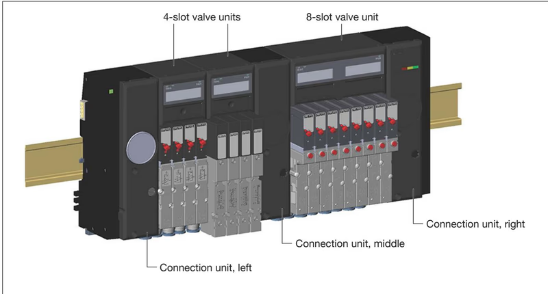
Pneumatic supply and deaeration for the valve block take place through dedicated connection units positioned at the ends and within the manifold string. Article 20138371 utilizes a left connection unit (PSU-L), a right connection unit (PSU-R), and one central intermediate feed module (PSU-M).
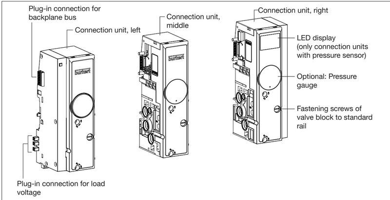
Intermediate Feed Requirement
According to Burkert Type 8647 engineering rules, an intermediate pneumatic feed is mandatory after every 24 valve functions when using standard single valves, and mandatory after every 16 valve functions when using 2x 3/2-way double valves. Because article 20138371 incorporates 12 double valves (24 valve functions total), one intermediate feed module (PSU-M, width 33 mm) is integrated into the valve island to preserve pneumatic flow rates and switching dynamics across all stations.
Port assignments on the connection units are organized as follows:
Each of the 12 valve slots is populated with a Type 6524 2x 3/2-way solenoid valve. Each unit contains two independent Type 6144 flipper pilot valves operating on a pneumatic seat amplifier. The seat valve principle delivers short switching times (12 ms opening, 20 ms closing) and low power consumption at operating pressures up to 10 bar.
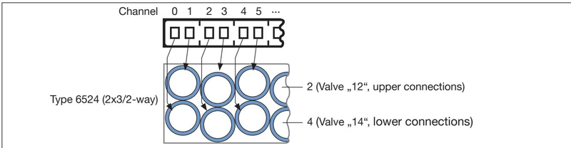
Working ports 2 and 4 are configured directly on the bottom face of the pneumatic base modules via push-in couplings sized for 6 mm outer diameter (D6) tubing:
Manual Override Operation
Each pilot valve is fitted as standard with a mechanical manual override on the valve body. To prevent accidental sustained operation, overrides must be set to neutral position for regular bus-controlled service. Push function acts as a momentary key; push and turn locks the valve in its energized state.
Article 20138371 belongs to the Revision 2 (REV.2) platform of Type 8647 AirLINE SP. REV.2 incorporates mechanical and pneumatic enhancements over the legacy REV.1 series:
Component Compatibility Limitation
Single valves and sub-base gaskets are not cross-compatible between REV.1 and REV.2. When maintaining or replacing valves on article 20138371, only REV.2 components with FM20 flange interface (or 2x 3/2-way double valves rated for REV.2) must be used.
Type 8647 AirLINE SP integrates directly into the backplane bus of Siemens SIMATIC ET 200SP and ET 200SP HA. Communication between the central controller (PLC/DCS) and the valve island is established via the ET 200SP interface module using PROFINET IO or PROFIBUS DP.
Electrical connections for load voltage (24 V DC), backplane communication, and functional grounding are completed automatically as the valve units latch onto the standard rail adjacent to the Siemens BaseUnits. The load bus requires compliance with specific engineering guidelines:
Dedicated Load Power Supply
A light-colored Siemens BaseUnit (type code BU...D or BU...D/T) must be installed immediately to the left of the Type 8647 valve block. This opens a new potential group and isolates the valve load voltage from other peripheral modules, guaranteeing adherence to the ±10% voltage tolerance limit required by the pilot solenoids.
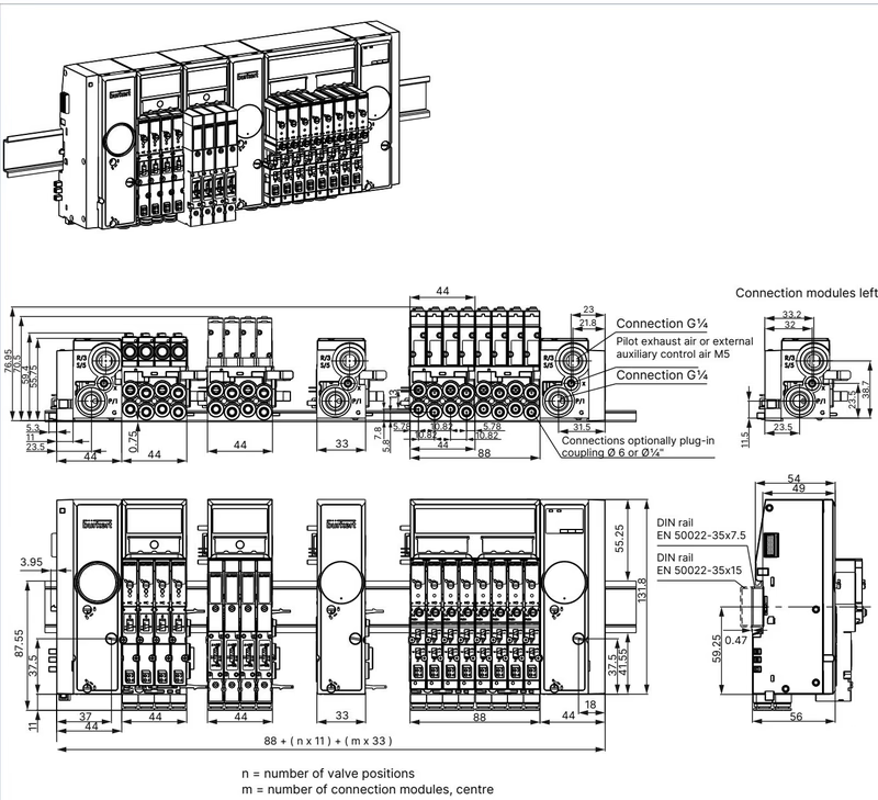
The total installation width of the pneumatic valve block is determined by the combination of connection units and valve slots: $$\text{Total Width} = W_{\text{PSU-L}} + (n \times 11\text{ mm}) + (m \times 33\text{ mm}) + W_{\text{PSU-R}}$$ For article 20138371:
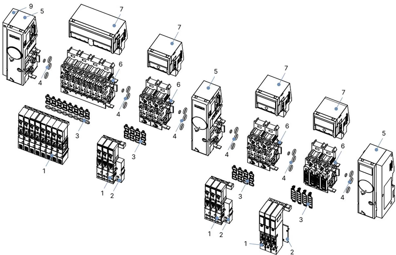
| Item | Description | Specification | Article No. |
|---|---|---|---|
| 1 | Replacement valve Type 6524 | 2x 3/2-way NC, 24 V DC, 2.5-10 bar, with manual override (REV.1/REV.2) | 204710 |
| 1 | Replacement valve Type 6524 | 2x 3/2-way NC, 24 V DC, 2.5-10 bar, without manual override (REV.1/REV.2) | 300818 |
| 2 | Valve slot cover plate | For Type 6524 2x 3/2-way valve (REV.2) | 661092 |
| 2 | Electrical connection cover | For unused electronic base module slots | 653670 |
| 3 | Valve profile seal set FM20 | For Type 6524 2x 3/2-way valve (set of 12) | 20016305 |
| 4 | Module seal set MP16 | For pneumatic base modules REV.2 (set of 4) | 20024339 |
| 5 | Intermediate feed unit PSU-M | 11 mm width per station, G 1/4 connection, REV.2 | 20030063 |
| 5 | Left supply unit PSU-L | 11 mm, G 1/4 connection, REV.2 | 20030062 |
| 5 | Right supply unit PSU-R | 11 mm, G 1/4 connection, REV.2 | 20030064 |
| 6 | Pneumatic base module | 4-fold, 11 mm, D6 push-in, FM20, REV.2 | 20040334 |
| 7 | Electronic base module PQ4VS4 | 4-fold, 11 mm, for double valves | 20040550 |
| 7 | Electronic base module PQ8VS8 | 8-fold, 11 mm, for double valves | 20040556 |
| 9 | Interface unit set left | Replacement interface module for Type 8647 | 20029826 |
Explore similar products in our catalog