

PN16

BURKERT 20139294 (Type 8652) is a 4-valve AirLINE pneumatic valve island with Industrial Ethernet, LC display, integrated check valves, pneumatic HotSwap, aluminium AirLINE Quick plate, and 24 V DC operation.
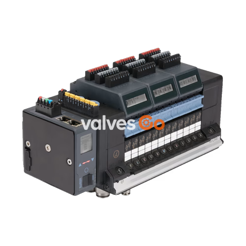
BURKERT 20139294 (Type 8652) is an electro-pneumatic AirLINE valve island configured with 4 valve slots, developed specifically for process automation tasks. The pre-configured unit incorporates four 3/2-way normally closed (circuit function CF-C) servo-assisted solenoid valves, an anodised aluminium AirLINE Quick baseplate adapter for control cabinet floor mounting, and dual RJ45 Industrial Ethernet communication ports that support PROFINET IO, EtherNet/IP, Modbus TCP, EtherCAT, and CC-Link IE Field Basic.

Equipped with integrated check valves in exhaust ducts 3 (R) and 5 (S), the valve terminal prevents unexpected pilot actuation triggered by backpressure spikes during valve switching. The integrated pneumatic HotSwap function in pressure supply channel 1 (P) permits live valve replacement while the pneumatic pressure supply remains active.
| Specification Parameter | Value / Execution for Article 20139294 |
|---|---|
| Valve Island Type | Type 8652 AirLINE |
| Order Code (Article No.) | 20139294 |
| Number of Valve Stations | 4 PCE (11 mm station width) |
| Valve Configuration (Positions 1 to 4) | 3/2-way solenoid valve, CF-C normally closed |
| Communication Interface Hardware | 2 × RJ45 female connectors (interfaces X1 and X2) |
| Supported Communication Protocols | Industrial Ethernet (PROFINET IO, EtherNet/IP, Modbus TCP, EtherCAT, CC-Link IE Field Basic) |
| Pneumatic Supply Connection (Port 1 / P) | D10 push-in coupling, nickel-plated brass |
| Pneumatic Working Connections (Ports 2, 4) | D6 push-in coupling, nickel-plated brass |
| AirLINE Quick Adapter Material | Anodised aluminium |
| Auxiliary Pilot Air Configuration | Internal supply |
| Intermediate Supply Modules | 0 PCE (without intermediate air feed) |
| Operating Pressure Range | -1.0 bar to 10.0 bar (vacuum to 10 bar) |
| Auxiliary Pilot Pressure Range | 3.0 bar to 10.0 bar |
| Nominal Air Flow Rate QNn | 310 l/min (at +20 °C, 6 bar inlet, 1 bar pressure drop; ~3% flow reduction with HotSwap) |
| Valve Switching Time | Opening: 15 ms, Closing: 15 ms (measured per ISO 12238) |
| Operating Voltage | 24 V DC (±10%, residual ripple max. 1 Vss) |
| Electrical Power per Valve Coil | 0.7 W nominal (0.175 W after electronic power reduction) |
| Rated Current per Valve Coil | 29 mA nominal (10 mA after power reduction) |
| Digital Inputs on Electronic Module | 0 (without DI module) |
| Duty Cycle | 100% ED continuous operation |
| Operating Medium | Dry, lubricated or non-lubricated compressed air, neutral gases (ISO 8573-1:2010 Class 7.4.4, 5 μm filter recommended) |
| Medium and Ambient Operating Temperature | -10 °C to +55 °C |
| Storage Temperature | -20 °C to +60 °C |
| Housing Materials | Polyamide (PA) body; NBR and PUR seals |
| Ingress Protection Rating | IP20 standalone; IP65 when mounted onto closed cabinet with AirLINE Quick plate |
| Electrical Safety Class | Class III according to DIN EN 61140, VDE 0140 |
| Conformity & Certification | CE, UL Listed (UL 61010-1, CAN/CSA-C22.2 No. 61010-1), NEMA 250 Type 4X (in closed enclosure with stainless steel variant) |
AirLINE Quick allows direct fastening of the valve island to the floor or wall of the control cabinet. All pneumatic connection lines pass through the cabinet base, eliminating separate bulkhead pass-through fittings and external tubing inside the enclosure.
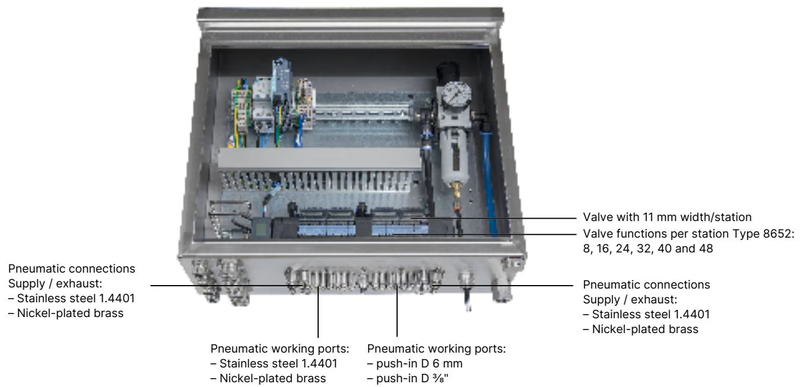
| Feature | AirLINE Quick Specification |
|---|---|
| Adapter Plate Material | Anodised aluminium (article 20139294 execution) or stainless steel 1.4301 |
| Pneumatic Port Material | Nickel-plated brass (article 20139294 execution) or stainless steel 1.4401 |
| Available Station Capacities | 8, 16, 24, 32, 40, and 48 valve functions |
| Supply / Exhaust Ports | Push-in connector D10 mm (or 3/8") |
| Working Ports | Push-in connector D6 mm (or 1/4") |
| Mounting Position | Cabinet bottom or cabinet side wall |
Type 8652 valve islands utilize Type 6534 pneumatic valves piloted by Type 6164 micro-solenoids. Article 20139294 is fitted with four circuit function C valves (3/2-way normally closed).
Circuit Function C (CF C)
Servo-assisted 3/2-way solenoid valve with manual override. In de-energised state, working port 2 is connected to exhaust duct 3, while supply port 1 remains closed. Energising the coil routes pilot air to open supply port 1 to working port 2.
The integrated HotSwap check mechanism in the subbase allows individual valves to be removed and replaced during live operation without depressurizing the main air header. Insertion of a replacement valve unseats the internal check seal, restoring supply to the valve slot. The presence of the HotSwap mechanism reduces nominal flow capacity by approximately 3%.
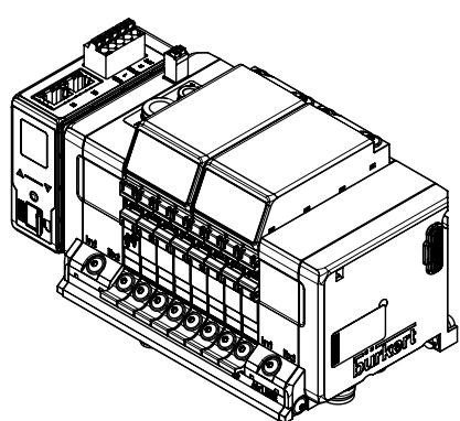
| Variant | A (mm) | B (mm) | C | m | n |
|---|---|---|---|---|---|
| 4-fold (Article 20139294) | 66 | — | 4 × M5 | 3 | 1 |
| 8-fold | 35 | 111 | 8 × M5 | 7 | 2 |
| 12-fold | 77 | 154 | 10 × M5 | 11 | 3 |
Mounting may be carried out either on a standard DIN rail (EN 50022 35 × 7.5 mm or 35 × 15 mm) or fastened directly via M5 screws.
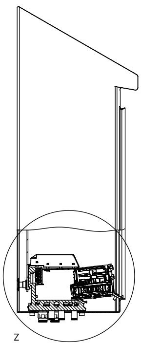
Installation Clearance for HotSwap
When installing the valve island inside an enclosure, maintain the minimum specified clearance between the front edge of the valve island and the cabinet door. This clearance ensures sufficient space to pivot and withdraw individual Type 6534 valves during live maintenance.
Type 8652 separates electronic control power from the pneumatic actuator coil power to support safety shutdowns and suppress switching transients.
| Pin | Wire Colour | Signal Assignment |
|---|---|---|
| 1 | Red | +24 V DC (logic power) |
| 2 | White | CAN_H (büS connection) |
| 3 | Green | SHIELDING |
| 4 | Blue | CAN_L (büS connection) |
| 5 | Black | 0 V DC (GND) |
Maximum cable cross-section: ≤ 1.5 mm².
| Clip | Wire Colour | Signal Assignment |
|---|---|---|
| 1 | Red | AUX 24 V (valve coil supply) |
| 2 | Black | 0 V DC (GND) |
Independent Supply Requirement
The communication module electronics and the pneumatic solenoid valves must be supplied by independent circuits to permit unpowered actuator interlocks without disrupting network communication.
| Pin | Industrial Ethernet Signal Assignment |
|---|---|
| 1 | TX+ (Transmit Data +) |
| 2 | TX- (Transmit Data -) |
| 3 | RX+ (Receive Data +) |
| 4 | N.C. (Not connected) |
| 5 | N.C. (Not connected) |
| 6 | RX- (Receive Data -) |
| 7 | N.C. (Not connected) |
| 8 | N.C. (Not connected) |
Type 8652 incorporates an illuminated LC display that outputs diagnostic messages in clear text and graphic symbols, displaying channel status, supply voltage deviations, and cycle counters directly at the terminal.
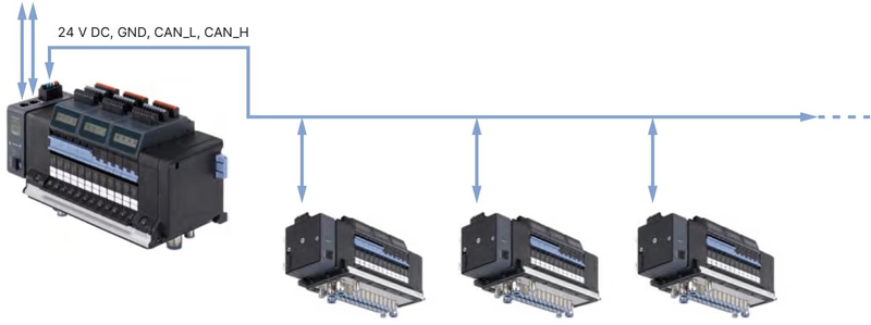
In field topologies, an AirLINE Type 8652 equipped with an Industrial Ethernet gateway acts as the primary master station, communicating with PLC automation architectures while coordinating slave valve islands over büS/CANopen communication links.
Device configuration, cyclical process image parameterization, diagnostic logging, and firmware maintenance are conducted through Bürkert Communicator software (Type 8920) on the Efficient Device Integration Platform (EDIP).
| Circuit Function | Nominal Width (mm) | QNn Air (l/min) | Pressure Range (bar) | Opening Time (ms) | Closing Time (ms) | Operating Voltage | Order Code (incl. screws) |
|---|---|---|---|---|---|---|---|
| CF C (3/2-way NC) | 4 | 270 | Vac to 10 | 15 | 15 | 24 V DC | 20102334 (Spare kit: REF_20088974) |
| CF C (2 × 3/2-way NC) | 4 | 270 | Vac to 10 | 15 | 15 | 24 V DC | 301374 (Spare kit: REF_296031) |
| CF D (2 × 3/2-way NO) | 4 | 310 | Vac to 10 | 15 | 15 | 24 V DC | 301375 (Spare kit: REF_296032) |
| CF H (5/2-way) | 4 | 290 | Vac to 10 | 20 | 25 | 24 V DC | 301376 (Spare kit: REF_296033) |
| CF Z (5/2-way impulse) | 4 | 290 | Vac to 10 | 20 | 25 | 24 V DC | 301377 (Spare kit: REF_296034) |
| CF L (5/3-way locked) | 4 | 275 | Vac to 10 | 15 | 15 | 24 V DC | 301380 (Spare kit: REF_296036) |
| CF M (5/3-way pressurized) | 4 | 300 | Vac to 10 | 20 | 20 | 24 V DC | 301379 (Spare kit: REF_296035) |
| CF N (5/3-way exhausted) | 4 | 300 | Vac to 10 | 20 | 20 | 24 V DC | 301381 (Spare kit: REF_296039) |
| Dummy Valve Slice | — | — | — | — | — | — | 335779 (Spare kit: REF_327614) |
Electrical Disconnection in Explosive Atmospheres
Do not connect or disconnect electrical wiring terminals when an explosive atmosphere is present. De-energize all circuits before servicing. Terminal connectors for 24 V DC power, SIA interlocks, EVS, and digital inputs may only be unplugged in de-energized conditions unless the area has been verified to be non-hazardous.
HotSwap in Hazardous Environments
HotSwap valve replacement must not be performed while a potentially explosive atmosphere is present. HotSwap procedures are permitted only when testing confirms that the ambient atmosphere is free of explosive gas or combustible dust concentrations.
When ordered with Ex-protection options (code PX68 or PU17), Type 8652 complies with:
Explore similar products in our catalog


