

PN16

BURKERT 20142853 is an 8-bank AirLINE SP Type 8647 REV.2 valve island with stainless steel AirLINE Quick base, G 1/4 ports, D6 push-in connections, P HotSwap, check valves in 3/5, and Siemens SIMATIC ET 200SP integration.
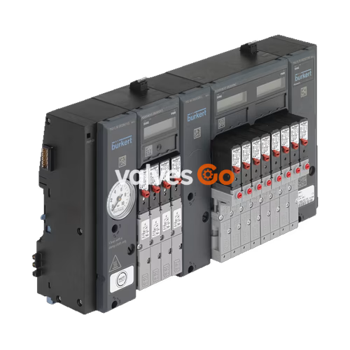
BURKERT 20142853 is an 8-bank AirLINE SP Type 8647 electropneumatic valve island configured for direct integration into Siemens SIMATIC ET 200SP and ET 200SP HA distributed I/O systems. Built in Generation Revision 2 (REV.2) with an 11 mm station pitch, it features an AirLINE Quick stainless steel base adapter plate with bottom-facing D6 push-in working connections and G 1/4 supply ports. The unit incorporates pneumatic HotSwap on supply channel 1 (P) and integrated check valves in exhaust ports 3 (R) and 5 (S), supporting operating pressures from 2.5 bar to 10 bar across an ambient operating temperature range of 0 °C to +55 °C.
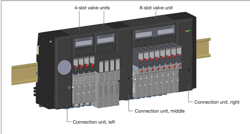
AirLINE SP Type 8647 operates as a combined electro-pneumatic automation platform that latches directly into the Siemens SIMATIC backplane bus. Electrical connections for load voltage, backplane communication, and functional grounding are established automatically upon mechanical engagement with the adjacent SIMATIC ET 200SP BaseUnits. Configuration and parameterization occur natively within Siemens engineering environments such as TIA Portal (via HSP or GSDML), SIMATIC STEP 7 Classic (via HSP or GSD), and SIMATIC PCS 7 (via Hardware Update Package HUP).
Station Power Supply Rule
Install a light-colored BaseUnit (BU...D or BU...D/T) directly to the left of the valve block to provide a dedicated load voltage feed. For SIMATIC ET 200SP HA installations, this separate power supply segment is mandatory. Load voltage tolerance is ±10% at 24 V DC, which must be observed to prevent undervoltage trips on pilot solenoid coils.
Integration constraints between the distributed I/O families must be evaluated during engineering:
| System Characteristic | SIMATIC ET 200SP Station | SIMATIC ET 200SP HA Station |
|---|---|---|
| Hardware mounting | Standard DIN rail (TH 35) | ET 200SP HA profile rail |
| BaseUnit upstream of valve block | Recommended (BU...D or BU...D/T) | Mandatory (BU...D or BU...D/T with cover) |
| Multiple valve blocks per station | Yes (with separate power feed) | No (maximum 1 valve block per station) |
| Expansion modules to the right | Permissible (light BaseUnit required) | Not permitted (must terminate with server module) |
| AirLINE Quick base adaptation | Permissible | Not supported due to mechanical layout |
| Engineering tools | TIA Portal (HSP/GSDML), STEP 7 (HSP/GSD) | PCS 7 (HUP) from V9.0 SP2, GSDML |
BURKERT 20142853 includes the AirLINE Quick base adapter constructed from stainless steel (1.4301 / 1.4401). Instead of routing pneumatic tubing through external cabinet glands, the AirLINE Quick plate installs directly into a rectangular cut-out at the bottom of the control cabinet. The valve block sits inside the enclosure while pneumatic supply, exhaust, and all D6 working lines exit directly downwards from the cabinet floor.
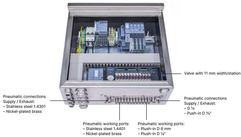
This mounting method eliminates individual tube feed-through glands, decreases internal cabinet volume requirements, and achieves an IP65 enclosure seal (UL Type 4X verified in closed cabinets). When mounted with AirLINE Quick, the rigid metal adapter plate carries the mechanical load, supporting the standard DIN rail and attached ET 200SP electronic slices.
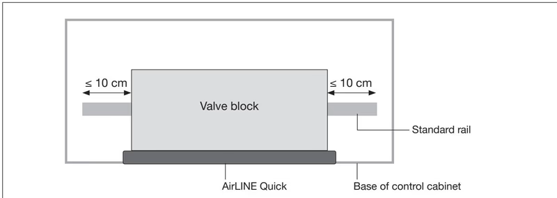
Cabinet Base Installation Requirements
Ensure the cabinet cut-out is burr-free prior to seating the sealing gasket into the AirLINE Quick plate groove. Fix the external stability plate using M5×10 screws tightened to 2.0 Nm. Rail projection beyond the valve block perimeter must not exceed 10 cm on either side.
The 8-bank pneumatic assembly operates over a pressure range of 2.5 bar to 10 bar using filtered, neutral gaseous media (ISO 8573-1:2010 Class 7.4.4 with 5 µm particle limits). Monostable pilot valves (Type 6524 3/2-way and Type 6525 5/2-way) deliver a nominal flow rate (QNn) of 300 l/min. Double valves (Type 6524 2×3/2-way) also deliver 300 l/min.
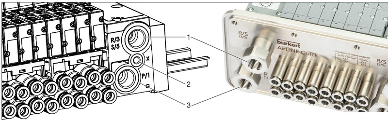
| Connection Position | Marking / Identification | Function | Thread / Dimension |
|---|---|---|---|
| Position 1 | R/3, S/5 | Common deaeration / exhaust ducts | G 1/4 (internal thread) |
| Position 2 | X | Auxiliary pilot air / pilot exhaust | M5 |
| Position 3 | P/1 | Main compressed air supply | G 1/4 (internal thread) |
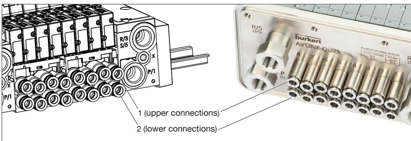
Pneumatic working lines are mapped at the individual valve positions:
| Port Location | 3/2-Way Valve (Type 6524) | 2×3/2-Way Valve (Type 6524) | 5/2-Way Valve (Type 6525) |
|---|---|---|---|
| Upper port 1 | Not used (remains plugged) | Working port 2 (A) | Working port 2 (A) |
| Lower port 2 | Working port 2 (A) | Working port 4 (B) | Working port 4 (B) |
Tightening Torques for Connections
Adhere to defined port torques during assembly: G 1/4 supply ports P and R/S require 4.0 Nm to 7.0 Nm (maximum 20 Nm); M5 pilot ports require 1.0 Nm to 1.2 Nm (maximum 3.0 Nm); M7 push-in connectors require 1.75 Nm to 2.25 Nm (maximum 4.0 Nm); valve block rail clamping screws require 1.8 Nm.
BURKERT 20142853 features integrated P-channel HotSwap check valves. Individual valves can be unscrewed and replaced while the main air supply remains pressurized. In Generation REV.2, the internal HotSwap check valve geometry reduces nominal flow by approximately 20% (improved from up to 50% flow reduction in REV.1). Integrated non-return check valves in exhaust ducts 3 (R) and 5 (S) prevent backpressures from migrating into adjacent actuators during safety shutdown or high-cycle exhausting.
Operational Safety Warning
Before replacing pilot valves on modules without P HotSwap, depressurize and vent all feed lines. Under P HotSwap operation, detaching a valve depressurizes ports A or B, which can cause connected actuators to move unexpectedly. Secure all mechanical actuators against movement before service.
BURKERT 20142853 belongs to Generation Revision 2 (REV.2). REV.2 incorporates significant mechanical and pneumatic design standardizations compared to earlier REV.1 units:
| Mechanical / Pneumatic Feature | Generation REV.1 | Generation REV.2 (Model 20142853) |
|---|---|---|
| Push-in collet release ring color | Black | Blue |
| Working port channel arrangement | Parallel alignment | Wavy (staggered) alignment |
| Pilot valve interface flange | Flange profile FM14 (single valves) | Standardized flange profile FM20 |
| Double valve interface flange | Flange profile FM20 | Standardized flange profile FM20 |
| Flow restriction with P HotSwap | Up to 50% reduction | Approximately 20% reduction |
| Type label markings | Standard marking without revision note | Explicit label designation "Rev.2" |
Flange Interface Compatibility
Single valves Type 6524 (3/2-way) and Type 6525 (5/2-way) with REV.1 FM14 flanges cannot be mounted onto REV.2 pneumatic base modules. REV.2 base modules accept only standardized FM20 replacement valves. Double valves Type 6524 (2×3/2-way) share the FM20 pattern and remain mechanically interchangeable.
The valve block draws coil power directly from the 24 V DC power bus of the SIMATIC ET 200SP BaseUnits. Power consumption is 0.8 W per single valve coil (1.6 W per 2×3/2-way valve). All electronic base modules contain electronic self-resetting short-circuit fuses and module-level blow fuses.
Three functional methods exist for safety-related valve shutdown:
EVS Wiring Restriction
Connect the EVS terminal only to potential-free switching contacts rated for 1.5 A at 24 V DC. Do not apply external voltage to EVS terminals. Never link EVS terminals from multiple modules in parallel; each module requires its own dedicated isolated contact. Limit wiring run to a maximum of 2 m within the same control cabinet.
Electronic base modules (PQ modules) communicate operational data through the Siemens backplane bus and display real-time statuses on dual LC displays. Channel output states, position feedbacks, and active system modes (such as PROFIenergy or active EVS shutdown) are presented graphically.
Each valve channel provides two separate 32-bit switching cycle counters:
Counters persist in remanent memory and can be evaluated or reset acyclically using SIMATIC data records DS 130 (pilot counter read), DS 131 (actuator counter read), and DS 132 (counter reset). Predictive maintenance limits can be parameterized to trigger control alarms when defined operating thresholds are reached.
Maintenance and modular expansion of the 8-bank BURKERT 20142853 assembly must utilize genuine REV.2 spare components:
| Component Description | Circuit Function / Specification | Order Article No. |
|---|---|---|
| Type 6524 Solenoid Valve (REV.2) | 3/2-way NC, 2.5–10 bar, 24 V DC, manual override | 20029918 |
| Type 6524 Solenoid Valve (REV.2) | 3/2-way NO, 2.5–10 bar, 24 V DC, manual override | 20029919 |
| Type 6524 Solenoid Valve (REV.2) | 3/2-way NC, Vac–7 bar, auxiliary pilot air | 20029923 |
| Type 6525 Solenoid Valve (REV.2) | 5/2-way, 2.5–10 bar, 24 V DC, manual override | 20029920 |
| Type 6524 Double Valve (REV.1/REV.2) | 2×3/2-way NC, 2.5–10 bar, 24 V DC, manual override | 204710 |
| Blanking cover plate (REV.2) | For unused slots: Type 6524/6525 REV.2 & 2×3/2-way | 661092 |
| Electrical connector cover | Covers unused electrical socket on PQ module | 653670 |
| Spare profile valve seals FM24 | For Type 6524 3/2-way REV.2 (pack of 12) | 20024336 |
| Spare profile valve seals FM20 | For Type 6524 2×3/2-way & Type 6525 REV.2 (pack of 12) | 20016305 |
| AirLINE Quick blind plate | 8-fold blind plate covering cut-out | 20057390 |
| Tube support sleeves | For push-in D6 PU flexible tubing (pack of 10) | 20099400 |
Explore similar products in our catalog


