Dry Steam Discharge

BURKERT 20150029 Type 8640 modular valve island for pneumatics. Features 16.5 mm width per station, G 3/8 pressure port, IP20 protection, and 2-10 bar operating pressure.
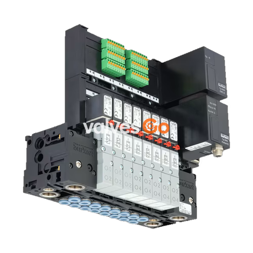
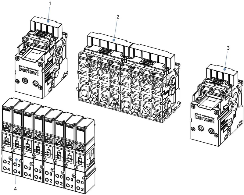
BURKERT 20150029 Type 8640 modular valve island for pneumatics is designed to solve diverse and complex control problems through its systematic modular construction and combination of pneumatic and electrical interfaces. By assembling a row of pneumatic modules with different numbers of valves, 2 to 24 valve functionalities can be realized on a single valve unit.
Bodies and connection modules are constructed from polyamide plastic and are assembled using built-in snap connectors. The system features a modular configuration and provides flexibility in the control cabinet when used with the AirLINE Quick adapter.

The following specifications apply to the 16.5 mm width per station configuration:
| Product properties | Value |
|---|---|
| Body material | PA (polyamide), aluminium |
| Seal material | NBR |
| Width per station | 16.5 mm |
| Manual override | Standard |
| Number of valve slots | Max. 24 |
| Pressure range | Vac...10 bar |
| External supply air | >2 bar |
| Flow rate $Q_{Nn}$ value air | 700 l/min measured at +20 °C, 6 bar pressure at valve inlet and 1 bar differential pressure |
| Operating voltage | 24 V DC (±10% tolerance) |
| Nominal power of each valve | 2 W, 1 W |
| Operating medium | Oil-free or lubricated compressed dry air, neutral gases (5 μm filter recommended) |
| Degree of protection | IP20 (IP65 in closed control cabinets) |
| Working port | D 8 |
| Air supply connection 1 (P), 3 (R), 5 (S) | G 3/8 |
| Ambient temperature | 0 °C...+ 55 °C |
| Symbol | Description |
|---|---|
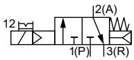 | Circuit function C (CF C) 3/2-way solenoid valve Servo-controlled, with manual override Normally closed |
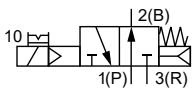 | Circuit function D (CF D) 3/2-way solenoid valve Servo-controlled, with manual override Normally open |
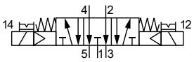 | Circuit function N (CF N) 5/3-way solenoid valve With manual override In middle position ports 2 and 4 exhausted |
Risk of injury due to high pressure and escaping medium
Switch off the pressure before working on the device or system. Vent or drain the pipes.
Risk of injury from quickly accelerating device parts
Before applying pressure to the valve, check all hose connections and fittings for tight, secure fit. Unconnected compressed air hoses can flap around.
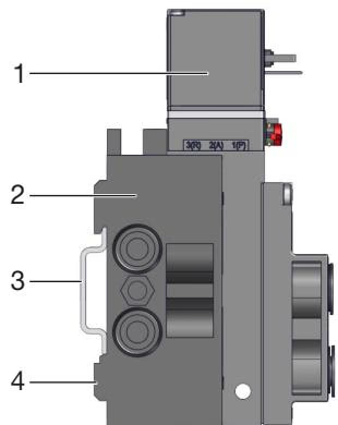
Standard rail installation:
Wall installation: Fasten the valve block directly to the wall with M4 screws.
Installation Position
The installation position of the valves is as required, preferably with the solenoid actuator on top.
Requirements for hose lines:
Risk of injury due to electric shock
Switch off voltage before working on the device or system. Secure against reactivation. When screwing in the solenoid with the cable plug, make sure that the seal is properly seated.