

PN16

BURKERT 307901 (Type 6281) is a 2/2-way servo-assisted solenoid valve featuring an NPT 3/4 stainless steel body, FKM seals, DN20 orifice, normally closed function, 0.2-16 bar operating pressure, and 24 V DC operation.
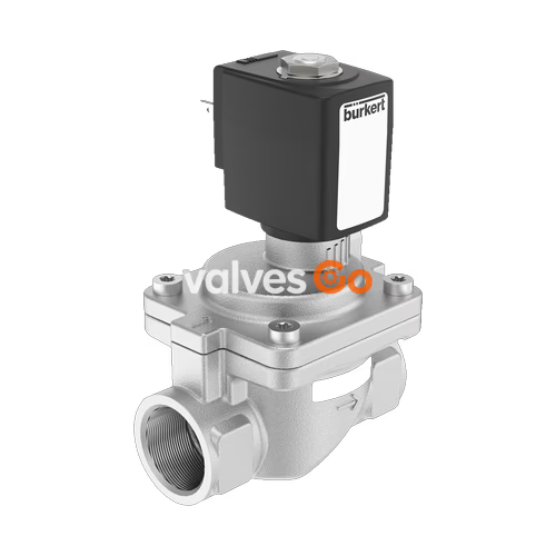
BURKERT 307901 (Type 6281) is a servo-assisted 2/2-way diaphragm solenoid valve configured with a cast stainless steel body 1.4408 (CF8M), FKM fluor rubber sealing, and an internal NPT 3/4 fluid connection. Operating under circuit function A, the valve remains closed in its de-energized rest state (normally closed, inlet port 1 P/NC). It controls neutral and aggressive liquids or gases compatible with stainless steel and FKM, delivering a water flow coefficient Kv of 8.5 m³/h and a gas nominal flow rate QNn of 9,100 l/min across an operating differential pressure range of 0.2 to 16 bar.
Actuation is powered by a 24 V DC solenoid coil using a central screw mounting design for vibration resistance. With Class H epoxy encapsulation, the valve operates at medium temperatures from 0 °C to +120 °C and ambient temperatures up to +55 °C. The unit is recognized under cURus (UL 429 and UL 429A) for industrial electrically operated valves and fire protection service, conforming to IP65 ingress protection when paired with a DIN EN 175301-803 Form A cable plug.
BURKERT 307901 requires a permanent differential pressure of at least 0.2 bar between inlet and outlet to actuate the main diaphragm. When the solenoid is energized, pilot flow opens the pilot seat (1.3 mm orifice), venting the chamber above the diaphragm and allowing line pressure to raise the diaphragm off the DN20 main orifice.
| Specification Parameter | Value / Characteristic |
|---|---|
| Valve Type / Family | Type 6281 EV (Generation EV) |
| Article Number | 307901 |
| Circuit Function | A (2/2-way, normally closed, inlet port 1 P/NC) |
| Main Valve Orifice (DN) | 20 mm (3/4") |
| Pilot Control Orifice | 1.3 mm |
| Port Connection | Internal thread NPT 3/4 |
| Nominal Pressure Rating | PN 16 (0.2 bar to 16 bar) |
| Flow Value Kv (Water, +20 °C, 1 bar Δp) | 8.5 m³/h |
| Flow Value QNn (Gas, air at +20 °C, 6 bar) | 9,100 l/min |
| Minimum Pressure Difference for Full Cross-Section | 0.5 bar |
| Operating Voltage / Current Type | 24 V DC (voltage tolerance ±10%) |
| Solenoid Coil Power Consumption | Cold power: 9.5 W; Warm power: 8 W |
| Solenoid Thermal Insulation Class | Class H (epoxy coil encapsulation) |
| Operating Duty Cycle | 100% ED continuous operation |
| Switching Time (Opening) | 0.1 to 1.5 s (measured per standard test conditions) |
| Switching Time (Closing) | 0.2 to 4 s (measured per standard test conditions) |
| Medium Temperature Range | 0 °C to +120 °C (FKM seal with epoxy coil) |
| Ambient Temperature Range | 0 °C to +55 °C |
| Maximum Permissible Viscosity | 21 mm²/s |
| Weight | Approximately 0.86 kg |
| Overall Installation Length | 80 mm |
INFO
A differential pressure of at least 0.2 bar is required for reliable valve opening and closing. A differential pressure of 0.5 bar is necessary to clear the entire DN20 flow cross-section.
The valve operates under Circuit Function A (CF A). In the unpowered condition, the pilot orifice is sealed by the spring-loaded magnetic armature, and fluid pressure builds up above the diaphragm to keep it firmly closed against the valve seat. Energizing the 24 V DC coil lifts the armature, relieving pressure above the diaphragm to the outlet side, which forces the main diaphragm upward.
| Circuit Function Symbol | Description |
|---|---|
| 2/2-way valve, normally closed (NC) | Circuit function A (CF A): 2/2-way solenoid valve, servo-controlled, normally closed. Inlet port 1 (P) to outlet port 2 (A). |
All wetted parts are selected for durability and compatibility with aggressive non-corrosive media. The body is cast stainless steel 1.4408, with magnetic components machined from corrosion-resistant ferritic stainless steel 1.4113.
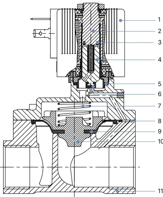
| Item No. | Valve Component | Material |
|---|---|---|
| 1 | Solenoid Coil | Epoxy (Class H encapsulation for FKM configurations) |
| 2 | Stopper | Stainless steel 1.4113 |
| 3 | Shading Ring | Silver (Ag) for stainless steel body variants |
| 4 | Magnetic Core (Armature) | Stainless steel 1.4113 |
| 5 | O-Ring | FKM (Fluor rubber) |
| 6 | Core Seal | FKM (Fluor rubber) |
| 7 | Return Spring | Stainless steel 1.4310 |
| 8 | O-Ring | FKM (Fluor rubber) |
| 9 | Diaphragm | FKM (Fluor rubber) |
| 10 | Diaphragm Holder | Polyphenylene sulfide glass-fiber reinforced (PPS GF40) |
| 11 | Valve Body | Stainless steel 1.4408 (CF8M) |
Per the manufacturer media compatibility guide, FKM seals are suitable for peroxide solutions, hot oils without additives, diesel and heating oil without additives, and washing lye.
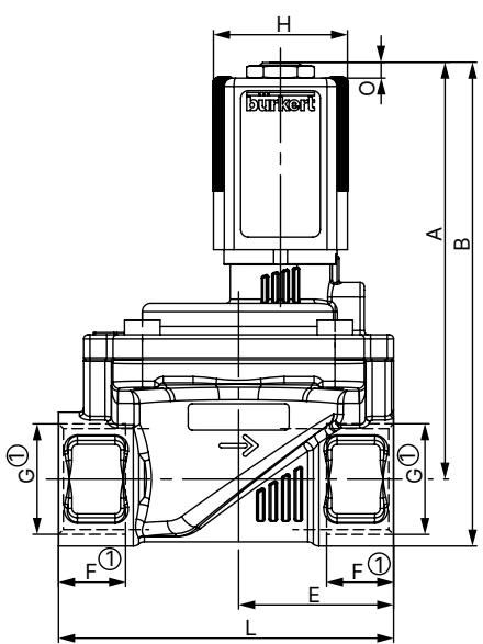
The dimensional values below specify the standard threaded variant for DN20 stainless steel bodies with NPT 3/4 process ports and size 5 / size 6 solenoids:
| Port Size | DN [mm] | A [mm] | B [mm] | C [mm] | D [mm] | E [mm] | F2 (NPT depth) [mm] | G2 [inch] | L [mm] | SW [mm] | N [mm] |
|---|---|---|---|---|---|---|---|---|---|---|---|
| NPT 3/4 | 20 | 99.6 | 115.6 | 60 | 74 | 37 | 14 | NPT 3/4 | 80 | 32 | 10 |
| NPT 1 | 20 | 102.1 | 122.6 | 60 | 74 | 37.5 | 16.8 | NPT 1 | 80 | 41 | 10 |
| Solenoid Coil Size | Width H [mm] | J [mm] | K [mm] | M [mm] | O [mm] |
|---|---|---|---|---|---|
| Coil Size 5 (32 mm width) | 32 | 20.5 | 45 | 41 | 3.4 |
| Coil Size 6 (40 mm width) | 40 | 23.5 | 51 | 41.4 | 3.8 |
All dimensions in mm unless otherwise indicated. For NPT threads, depth F2 and thread code G2 apply.
BURKERT 307901 complies with European directives, North American safety standards, and global quality requirements:
DANGER: System Pressure and Electrical Hazard
Before loosening pipes or removing the valve, depressurize the system and vent all lines. Disconnect power supply and secure against unintended restart before servicing.

Operational Reliability
During long periods of system downtime, execute at least 1 to 2 switching cycles per day to maintain diaphragm flexibility and functional reliability.
Electrical connection is established via a DIN EN 175301-803 Form A plug pattern.
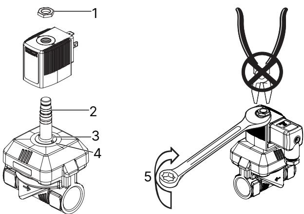
Fire Hazard: Coil Overheating
Never energize the solenoid coil without the valve body and armature guide tube installed. Operating the coil unmounted causes rapid overheating and leads to total coil destruction.
When removing or replacing the solenoid coil:
| Solenoid Type | Coil Width | Tightening Torque |
|---|---|---|
| AC10 | 32 mm or 40 mm | 5 Nm |
| AC19 | 42 mm | 10 Nm |
If the valve exhibits abnormal behavior during commissioning or operation, conduct the following systematic checks:
| Malfunction Symptom | Potential Root Cause | Corrective Action |
|---|---|---|
| Valve fails to open / no actuation | Power supply interrupted or incorrect voltage | Verify 24 V DC supply across terminals and check coil winding continuity. |
| Operating pressure out of bounds | Verify that fluid differential pressure is within 0.2 to 16 bar. | |
| Contamination in armature area | Disassemble coil and inspect armature guide tube; clean out particles. | |
| Valve fails to close | Diaphragm control bore clogged | Remove bonnet screws; clean the small pilot orifice in the FKM diaphragm. |
| Foreign matter under valve seat | Disassemble body and clean main valve seat and FKM seal surface. | |
| Valve manual override engaged | Check if optional manual lever (if fitted) is positioned in vertical bypass mode. |
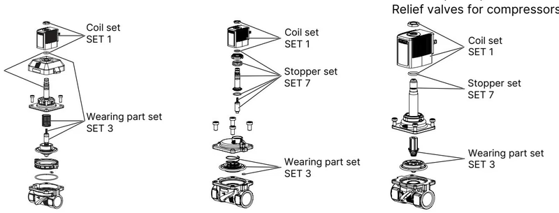
Spare parts for Type 6281 EV are ordered by specifying the device identification number 307901 and the required kit designation:
Cable plugs must be ordered separately. Compatible Type 2518 DIN EN 175301-803 Form A units include:
| Cable Plug Variant | Voltage Range | Article Number |
|---|---|---|
| Type 2518 without circuitry (standard AC/DC) | 0 to 250 V AC/DC | 314802 |
| Type 2518 with LED | 12 to 24 V AC/DC | 314812 |
| Type 2518 with LED and Varistor | 12 to 24 V AC/DC | 314820 |
| Type 2518 with Rectifier, LED, and Varistor | 12 to 24 V AC/DC | 314816 |
| Type 2509 without circuitry (standard connector) | 0 to 250 V AC/DC | 137943 |
Explore similar products in our catalog


