

PN16

Burkert 310016 (Type 6519) is a 5/2-way pneumatic solenoid valve with NAMUR flange interface, G 1/4 supply ports, 48 V DC coil, 900 l/min gas flow rate, and 2 to 10 bar operating pressure.
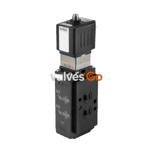
Burkert 310016 (Type 6519) is a 32 mm width 5/2-way pneumatic solenoid valve designed for pilot actuation of pneumatic actuators and process valves. Configured in valve circuit function W (normally open), inlet port 1 connects to outlet port 2, outlet port 4 connects to exhaust port 5, and exhaust port 3 is closed. Alternatively, when switched, inlet port 1 closes, and outlet ports 2 and 4 connect to exhaust port 5. The unit is electrically piloted by a 48 V DC solenoid coil and provides a nominal gas flow capacity (QNn) of 900 l/min across an operating pressure range of 2.0 to 10.0 bar.
| Specification Parameter | Technical Value |
|---|---|
| Model / SKU | 310016 |
| Product Type Family | 6519 |
| Overall Width | 32 mm |
| Valve Function | 5/2-way, Function W (normally open) |
| Fluidic Ports | 5 ports, 2 switching positions |
| Main Valve Orifice (DN) | 6.0 mm |
| Pilot Valve Orifice | 1.2 mm |
| Flow Capacity QNn (Gas) | 900 l/min |
| Operating Pressure Range | 2.0 bar to 10.0 bar |
| Nominal Operating Voltage | 48 V DC |
| Supply Connection | G 1/4 female thread |
| Working Port Connection | Flange interface NAMUR FM02 (left of supply) |
| Main Valve Material (Media Contact) | Polyamide (PA) |
| Valve Body Material (Environment) | Polyamide (PA) |
| Pilot Control Material | Polyamide (PA) |
| Main Valve Seal Material | Polyurethane (PUR) |
| Reset / Return Mechanism | Pneumatic spring + mechanical spring |
| Manual Override | Integrated |
| Electrical Interface | Plug pattern Form A according to DIN EN 175301-803 |
| Medium Temperature Range | -10 °C to +55 °C |
| Ambient Temperature Range | -25 °C to +55 °C |
| Ingress Protection Rating | IP65 (with suitable plug connector attached) |
Burkert 310016 incorporates a standardized NAMUR FM02 working port flange configuration situated to the left of the fluidic supply port. This interface permits direct mounting to quarter-turn pneumatic actuators conforming to VDI/VDE 3845 standards, eliminating the need for external inter-connecting tubing.
NAMUR Interface Standard
The FM02 flange interface mates directly to NAMUR-compliant actuator ports. Ensure mounting surfaces are clean and O-rings are seated flat before securing the fixing bolts.
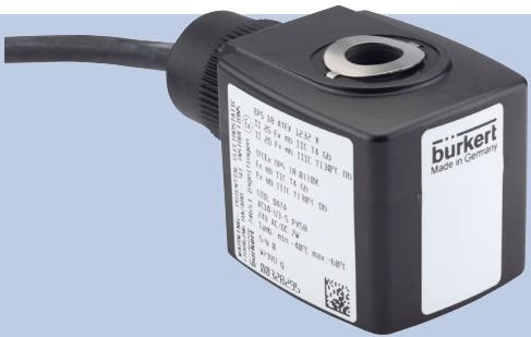
The valve utilizes an electrical pilot operator rated for 48 V DC. The electrical termination conforms to DIN EN 175301-803 Form A plug pattern.
Electrical Safety and Disconnection
Pressure and Static Hazard Instructions
When installed, heat dissipation from the pilot coil occurs through the valve body. The valve body provides cooling for the solenoid coil assembly:
Verify the following steps before initiating pressurized operation:
Under specified operating conditions, the Type 6519 pneumatic valve is maintenance-free. If operational errors occur, verify that pneumatic pressure is within 2.0 to 10.0 bar, supply voltage is 48 V DC, lines are free of blockages, and electrical connections are intact.
Storage and Disposal
Explore similar products in our catalog


