


Up to 99.8% Efficiency

BURKERT 312308 (Type 3285) is an electromotive 2-way globe proportional valve with G 3/4 connection, DN 12 orifice, oxide ceramics/FKM sealing, 24 V DC operation, and M12 5-pin büS fieldbus interface.
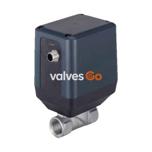
BURKERT 312308 (Type 3285) is an electromotive 2-way globe proportional valve designed for continuous fluid dosing and control of neutral gases and liquids. Driven by an integrated stepper motor, the valve regulates flow through precision ceramic control discs without requiring an external actuation control module. The stepper motor draws no electrical power in holding position, consuming less than 1 W when resting at any intermediate set-point stroke.
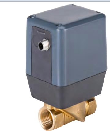
Article 312308 is configured with a stainless steel 1.4408 valve body, female G 3/4 port connections, a nominal seat diameter of 12 mm (7/16"), and an oxide ceramic disc seat sealed with FKM. It delivers a water flow coefficient (Kvs) of 3.9 m³/h across an operating pressure span of 0 to 6 bar(g). The integrated positioner module interfaces directly with digital fieldbus automation via the Bürkert system bus (büS) on a 5-pin M12 connector.
| Specification Parameter | Value for Article 312308 | Type 3285 Series Range |
|---|---|---|
| Port connection 1 | G 3/4 internal thread | G, NPT, Rc (1/2" to 1") |
| Orifice size / Seat diameter | DN 12 mm (7/16") | DN 8 mm to DN 25 mm |
| Flow coefficient Kvs (water) | 3.9 m³/h | 1.8 m³/h to 9.6 m³/h |
| Nominal pressure range | 0...6 bar(g) | 0...6 bar(g) (vacuum to -0.9 bar optional) |
| Fluid medium | Neutral gases and liquids | Neutral gases and liquids |
| Medium temperature range | 0 °C...+70 °C | -30 °C...+70 °C (EPDM), 0 °C...+70 °C (FKM, NBR) |
| Ambient temperature range | -10 °C...+60 °C | -10 °C...+60 °C |
| Operating voltage | 24 V DC ±10% (max. 10% ripple) | 24 V DC ±10% |
| Power consumption | < 1 W holding, max. 12 W moving | < 1 W holding, max. 12 W moving |
| Dead band of position control | ±0.5% (setting range 1:100) | ±0.5% (setting range 1:100) |
| Closing time | 4 s | 4 s |
| Protection class | IP50 | IP50 |
| Flow direction | Above seat | Above seat |
| Fluid viscosity | Max. 80 mm²/s (cSt) | Max. 80 mm²/s (cSt) |
| Valve body material | Stainless steel 1.4408 | Brass, Stainless steel 1.4408 |
| Seat seal material | Oxide ceramics / FKM | Oxide ceramics / FKM, EPDM, NBR |
| Control variant | Digital fieldbus positioner | Standard On/Off, Standard Control, Positioner, Process Controller |
The actuator assembly is completely isolated from the fluid flow path. The internal fluidic shut-off and metering mechanism relies on high-purity technical ceramics to achieve wear resistance during continuous modulation.
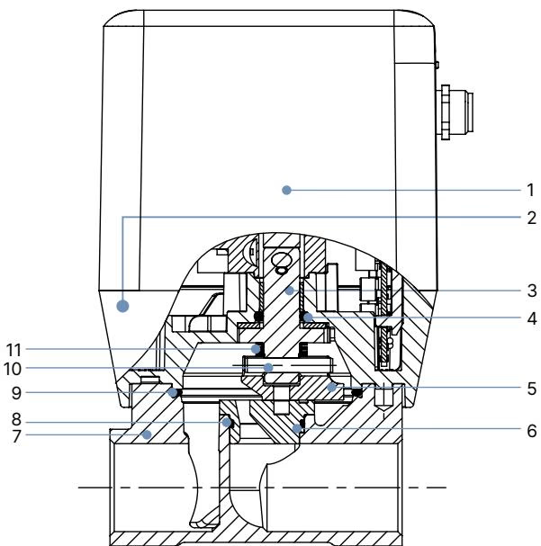
| Item No. | Component Element | Material Specification (Article 312308) | Alternative Series Materials |
|---|---|---|---|
| 1 | Housing cover | Polycarbonate (PC) | PC |
| 2 | Housing base | Polyphenylene sulphide (PPS) | PPS |
| 3 | Spindle | Stainless steel 1.4404 / 1.4401 | Stainless steel 1.4404 / 1.4401 |
| 4 | Spindle seal | FKM | EPDM, NBR |
| 5 | Disc | Technical ceramics | Technical ceramics |
| 6 | Valve seat | Technical ceramics | Technical ceramics |
| 7 | Valve body | Stainless steel 1.4408 | Brass |
| 8 | O-ring | FKM | EPDM, NBR |
| 9 | O-ring | FKM | EPDM, NBR |
| 10 | Parallel pin | Stainless steel 1.4401 | Stainless steel 1.4401 |
| 11 | Spring | Stainless steel / spring steel | Spring steel / stainless steel |
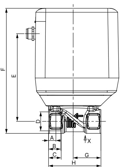
Dimensions for Type 3285 threaded variants are listed in millimeters (mm). Article 312308 corresponds to the G 3/4 thread row:
| Thread Standard | Connection D | A (mm) | B (mm) | C (mm) | E (mm) | F (mm) | G (mm) | H (mm) |
|---|---|---|---|---|---|---|---|---|
| NPT (ASME B 1.20.1) | NPT 1/2 | 8.2 | 13.7 | — | 97.0 | 138.0 | 31.0 | 58.0 |
| Rc (ISO 7-1) | Rc 1/2 | — | 13.7 | — | 97.0 | 138.0 | 31.0 | 58.0 |
| G (EN ISO 228-1) | G 1/2 | — | — | 14.0 | 97.0 | 138.0 | 31.0 | 58.0 |
| NPT (ASME B 1.20.1) | NPT 3/4 | 8.6 | 14.0 | — | 103.5 | 147.0 | 43.0 | 80.0 |
| Rc (ISO 7-1) | Rc 3/4 | — | 14.0 | — | 103.5 | 147.0 | 43.0 | 80.0 |
| G (EN ISO 228-1) [312308] | G 3/4 | — | — | 16.0 | 103.5 | 147.0 | 43.0 | 80.0 |
| NPT (ASME B 1.20.1) | NPT 1 | 10.2 | 16.8 | — | 108.5 | 156.5 | 49.0 | 95.0 |
| Rc (ISO 7-1) | Rc 1 | — | 16.8 | — | 108.5 | 156.5 | 49.0 | 95.0 |
| G (EN ISO 228-1) | G 1 | — | — | 18.0 | 108.5 | 156.5 | 49.0 | 95.0 |
Article 312308 operates as a digital fieldbus positioner valve variant. It communicates over the Bürkert system bus (büS) based on CANopen protocols using an A-coded 5-pin M12 circular plug.
| Pin Number | Signal Configuration | Description |
|---|---|---|
| 1 | Shield | Cable shield connection |
| 2 | 24 V DC | Main power supply (+24 V DC ±10%) |
| 3 | GND | Power supply ground (0 V) |
| 4 | CAN_H | CANopen / büS communication high line |
| 5 | CAN_L | CANopen / büS communication low line |
Standard analogue positioner versions utilize an 8-pin A-coded M12 connector (Pin 1: 24 V DC, Pin 2: GND, Pins 3–5: internal büS parameterization, Pin 6: Set-point input +, Pin 7: Actual value output, Pin 8: Signal GND). Dual-loop process controller variants (D) feature an additional 5-pin M12 socket for an external 4...20 mA, 0...10 V, or frequency process transmitter input.
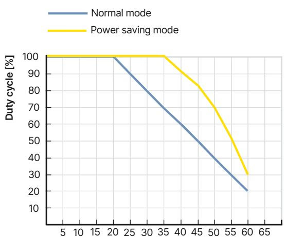
Motor duty cycle designates the operating time of the stepper drive during position changes, rather than total device power-on time. The motor switches on only when traversing between stroke positions.
Operating Limits and Duty Cycle
Stepper motor self-heating limits continuous adjustment cycles. High ambient temperatures increase internal thermal stress. Exceeding recommended duty cycle limits accelerates wear and reduces valve operating life. In energy-saving mode with reduced driving force, higher duty cycle limits apply.
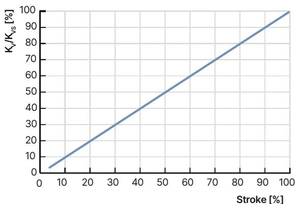
Type 3285 proportional valves maintain a linear flow characteristic when correctly sized against the piping system hydraulic resistance. Seat sizes range from 8 mm to 25 mm:
| Valve Function | Seat Size (DN) | Port Connection | Kvs Value Water (m³/h) | Operating Pressure [bar(g)] |
|---|---|---|---|---|
| Control valve | 8 | G 1/2 | 1.8 | 0...6 |
| Control valve | 10 | G 1/2 | 2.5 | 0...6 |
| Control valve [312308] | 12 | G 3/4 | 3.9 | 0...6 |
| Control valve | 15 | G 3/4 | 5.4 | 0...6 |
| Control valve | 20 | G 1 | 8.1 | 0...6 |
| Control valve | 25 | G 1 | 9.6 | 0...6 |
Kv calculations determine required valve flow capacities based on pressure drop conditions:
| Flow Condition | Kv Value for Liquids (m³/h) | Kv Value for Gases (m³/h) |
|---|---|---|
| Sub-critical: $p_2 > \frac{p_1}{2}$ | $K_v = Q \cdot \sqrt{\frac{\rho}{1000 \cdot \Delta p}}$ | $K_v = \frac{Q_N}{514} \cdot \sqrt{\frac{T_1 \cdot \rho_N}{p_2 \cdot \Delta p}}$ |
| Supercritical: $p_2 < \frac{p_1}{2}$ | $K_v = Q \cdot \sqrt{\frac{\rho}{1000 \cdot \Delta p}}$ | $K_v = \frac{Q_N}{257 \cdot p_1} \cdot \sqrt{T_1 \cdot \rho_N}$ |
Valve Sizing Recommendation
Select the seat size so that at maximum flow rate, the pressure drop across the fully opened valve represents at least 25% of the total system pressure loss (Δp_valve > 0.25 · Δp_total). A nominal Kvs value approximately 10% higher than the calculated operating Kv prevents characteristic distortion.
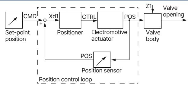
In the positioner configuration, the internal position controller continuously evaluates the digital set-point command (CMD) transmitted over the büS network against the actual stroke position (POS) reported by the integrated non-contact position sensor. If a control deviation (Xd1) occurs, the electronics drive the stepper motor to reposition the ceramic control disc until the deviation drops within the ±0.5% dead band. Integrated status LEDs indicate current operating states and physical valve travel end positions.
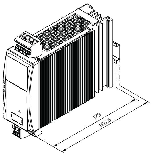
Type 3285 valves do not contain mechanical return springs. To secure a designated safety position upon power supply failure, the valve must be powered through the optional Type 1573 capacitive buffer module.
| Pin Number | Buffer Module Pin Configuration |
|---|---|
| 1 | Shield |
| 2 | 24 V DC (Power Input) |
| 3 | GND |
| 4 | CAN_H |
| 5 | CAN_L |
Upon loss of main line power, the buffer module provides an 18 V DC auxiliary voltage for several seconds. The valve electronics detect the voltage drop and drive the stepper motor to the configured safety shut-off position. Up to two Type 3285 valves can be supported by a single capacitive buffer module.
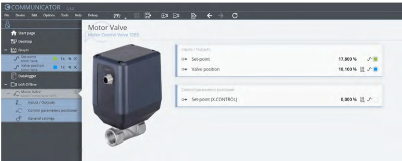
Parameter configuration, diagnostic logging, and calibration are performed via the Bürkert Communicator software tool (EDIP environment). Connection to a service PC requires an optional USB-büS interface stick:
| Accessory Description | Article Number |
|---|---|
| Power supply unit Phoenix Class 2 (Type 1573), 85...240 V AC / 24 V DC, 1.25 A, NEC Class 2 | 772438 |
| Power supply unit for DIN rail (Type 1573), 100...240 V AC / 24 V DC, 1 A, NEC Class 2 | 772361 |
| Power supply unit for DIN rail (Type 1573), 100...240 V AC / 24 V DC, 2 A, NEC Class 2 | 772362 |
| Power supply unit for DIN rail (Type 1573), 100...240 V AC / 24 V DC, 3.8 A, NEC Class 2 | 772898 |
| Capacitive buffer module (Type 1573) for safety shut-off position during power failure | 773440 |
| Cable Description | Article Number |
|---|---|
| M12 circular socket with cable, 8-pin, 2 m pre-assembled cable for analogue variants | 919061 |
| M12 circular socket with cable, 8-pin, 2 m pre-assembled shielded cable for analogue variants | 918991 |
| M12 cable shielded, 5-pin, 2 m pre-assembled cable for process actual value input signals | 559177 |
| Communication Accessory Description | Article Number |
|---|---|
| Bürkert Communicator software tool | Type 8920 |
| büS adapter, M12 socket 8-pin to M12 plug 5-pin | 773286 |
| USB-büS interface set 1 (Type 8923) with M12/micro-USB cables, terminating stick, and software | 772426 |
| USB-büS interface set 2 (Type 8923) with M12 cables, Y-distributor, and büS stick (0.7 m cable) | 772551 |
Explore similar products in our catalog


