


Up to 99.8% Efficiency

BURKERT 320460 (Type 3280) is an electromotive 2-way globe control valve with G 1/4 brass body, PEEK/EPDM seal, 0-6 bar operating pressure, 24 V DC supply, and integrated CANopen process controller.
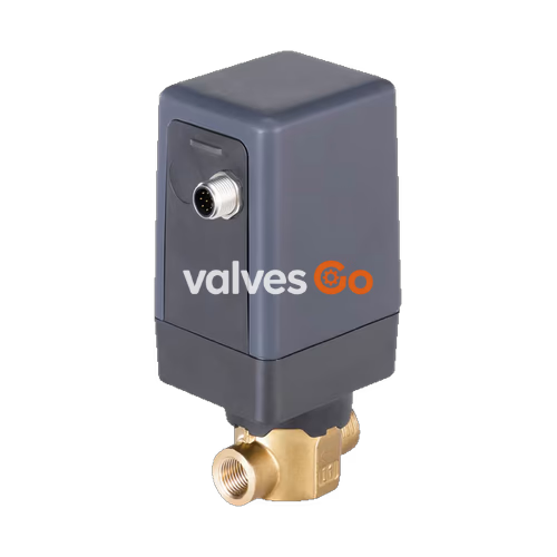
BURKERT 320460 (Type 3280) is an electromotive direct-acting 2-way globe control valve designed for dosing neutral liquids and gases in continuous control applications. The valve is driven by an internal linear stepper motor and integrates dedicated control electronics, eliminating the need for external actuation modules. To maintain a set opening position, the stepper motor consumes less than 1 W of holding power, reducing total plant electrical demand. Article 320460 is built with a brass body, G 1/4 internal thread, 1 mm seat orifice (Kv 0.03 m³/h), PEEK/EPDM seat seal, and an integrated process controller featuring a digital CANopen (büS) interface and a 4-20 mA sensor input.
Fluid flows below the seat against the closing direction, preventing water hammer and enabling stable continuous modulation with a closing time of 2.5 seconds and a position control dead band of ±0.5% (corresponding to a 1:100 setting range).
| Parameter | Specification |
|---|---|
| Valve Design | Direct-acting electromotive 2-way globe control valve |
| Article Number (SKU) | 320460 |
| Basic Type | 3280 |
| Nominal Seat Size | DN 1 (1 mm / 1/32") |
| Port Connection | G 1/4 internal thread (EN ISO 228-1) |
| Flow Coefficient (Kv) | 0.03 m³/h (water at +20 °C, Δp = 1 bar) |
| Operating Pressure Range | 0 to 6 bar(g) |
| Valve Seat Seal | PEEK / EPDM |
| Body Material | Brass |
| Actuator Housing | PC (cover) / PPS (base) |
| Fluid Temperature Range | 0 °C to +70 °C |
| Ambient Temperature Range | -10 °C to +60 °C (subject to duty cycle derating) |
| Operating Voltage | 24 V DC ± 10% (max. residual ripple 10%) |
| Power Consumption | < 1 W holding position; max. 8 W operating (DN 1 to DN 6) |
| Fluid Viscosity Limit | Max. 600 mm²/s (cSt) |
| Flow Direction | Below seat (against closing direction) |
| Closing Time | 2.5 s |
| Enclosure Rating | IP54 (with properly attached mating connectors) |
| Mounting Position | Any position, preferably with actuator upright |
| Total Unit Weight | Approx. 0.7 kg |
BURKERT Type 3280 complies with relevant EU Directives as detailed in the EU Declaration of Conformity.
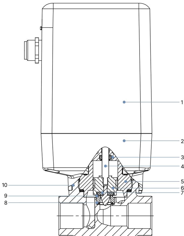
| Item No. | Component | Material |
|---|---|---|
| 1 | Housing cover | Polycarbonate (PC) |
| 2 | Housing base | Polyphenylene sulphide (PPS) |
| 3 | Spindle seal | EPDM / FKM / NBR |
| 4 | Spindle | Stainless steel 1.4305 |
| 5 | Upper valve body | Brass or stainless steel 1.4305 |
| 6 | Guided piston with parabolic plug | PTFE / Stainless steel 1.4305 |
| 7 | Elastomer seat seal | PEEK / EPDM (PEEK used for seat sizes 1 and 1.5 mm) |
| 8 | O-ring | EPDM / FKM / NBR |
| 9 | Valve seat | Stainless steel 1.4301 / 1.4305 |
| 10 | Valve body | Brass (AISI 316L stainless steel optional) |
Seat Seal Note
For seat sizes 1 mm and 1.5 mm, PEEK seat seals are used in combination with elastomer sealing elements. Seat tightness is reduced in these ultra-small orifice executions compared to soft elastomer seals.
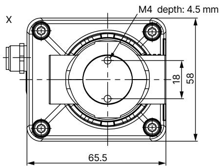
| Port Thread (D) | A | B | C | E | F | G | H |
|---|---|---|---|---|---|---|---|
| G 1/4 (320460) | — | — | 12 | 96.4 | 134.2 | 10 | 27.5 |
| NPT 1/4 | 5.8 | 10.0 | — | 96.4 | 134.2 | 10 | 27.5 |
| G 3/8 | — | — | 12 | 97.4 | 137.2 | 12 | 27.5 |
| NPT 3/8 | 6.0 | 10.3 | — | 97.4 | 137.2 | 12 | 27.5 |
| G 1/2 | — | — | 14 | 97.4 | 139.2 | 14 | 29.5 |
| NPT 1/2 | 8.2 | 13.7 | — | 97.4 | 139.2 | 14 | 29.5 |
Alternative Connection Forms
Type 3280 is also manufactured in sub-base (flange) configurations and cartridge configurations for direct block integration. Dimensions and cavity drawings are documented in the Type 3280 operating instructions.
BURKERT 320460 operates as a digital process controller execution. It features two M12 circular connectors: a 5-pin A-coded plug for power and digital communication (büS/CANopen), and a 5-pin A-coded socket for the external process variable input.
| Pin | Configuration | Function |
|---|---|---|
| 1 | Shield | Bus cable shielding |
| 2 | 24 V DC | Main operating power supply |
| 3 | GND | Power supply ground |
| 4 | CAN_H | CANopen dominant high line |
| 5 | CAN_L | CANopen dominant low line |
| Pin | Configuration | Function |
|---|---|---|
| 1 | 24 V DC | Sensor power supply output |
| 2 | Analogue IN | Process sensor signal: 4-20 mA (input impedance 60 Ω), 0-20 mA, 0-5/10 V (22 kΩ), or frequency (5-2000 Hz) |
| 3 | GND | Sensor ground |
| 4 | GND | Sensor ground (bridged internally to pin 3) |
| 5 | Not connected | Unassigned |
Standard on/off and positioner variants use an 8-pin A-coded M12 connector: Pin 1 (24 V DC), Pin 2 (Power GND), Pins 3/4/5 (Internal büS use for configuration via büS stick), Pin 6 (Signal input +), Pin 7 (Signal output actual value), Pin 8 (Signal GND).
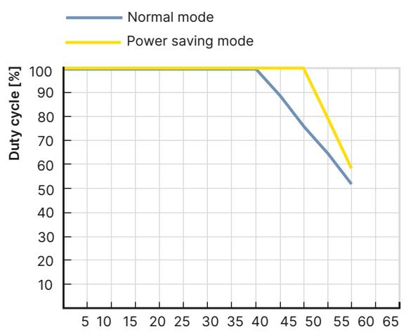
Duty Cycle Limits
In electromotive valves, duty cycle represents the active run time of the stepper motor, not the electrical power-on duration of the device. Motor self-heating limits continuous positioning movements. Frequent setpoint oscillations increase motor duty cycle and can reduce service life. Operating outside the permissible derating boundary risks thermal motor degradation.
| Valve Function | Seat Size (DN) | Port Connection | Kvs Value [m³/h] | Operating Pressure Range [bar(g)] |
|---|---|---|---|---|
| Control valve (320460) | 1.0 | G 1/4 | 0.030 | 0 to 6 |
| Control valve | 1.5 | G 1/4 | 0.065 | 0 to 6 |
| Control valve | 2.0 | G 1/4 | 0.130 | 0 to 6 |
| Control valve | 3.0 | G 1/4 | 0.300 | 0 to 6 |
| Control valve | 4.0 | G 3/8 | 0.500 | 0 to 6 |
| Control valve | 5.0 | G 3/8 | 0.750 | 0 to 6 |
| Control valve | 6.0 | G 3/8 | 0.900 | 0 to 6 |
| Control valve | 8.0 | G 1/2 | 1.500 | 0 to 6 |
| Control valve | 10.0 | G 1/2 | 1.900 | 0 to 6 |
To ensure stable control performance, the nominal seat diameter must be sized so that at maximum flow, a substantial fraction of the total system pressure loss occurs across the valve:
$$\Delta p_{\text{valve}} > 25% \text{ of total system pressure drop}$$
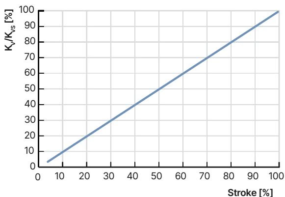
If the valve pressure drop is too small relative to piping resistance, the inherent linear valve characteristic will deform into an uneven, distorted system curve.
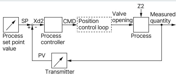
In the process controller configuration (device variant D), an integrated PID algorithm performs cascade control without requiring a supervisory PLC loop:
For applications requiring a defined fail-safe position during complete power failure, Type 3280 can be powered through the external capacitive buffer module (Type 1573, Ident 773440). Upon supply failure, the module delivers 18 V DC backup power for several seconds, enabling the actuator to travel to its pre-configured safety position (factory setting: fully closed). Up to three Type 3280 valves can connect to one module.
| Item Description | Article No. |
|---|---|
| Power supply unit Phoenix Class 2 (Type 1573), 85-240 V AC / 24 V DC, 1.25 A, NEC Class 2 (UL 1310) | 772438 |
| DIN rail power supply unit (Type 1573), 100-240 V AC / 24 V DC, 1.0 A, NEC Class 2 (UL 1310) | 772361 |
| DIN rail power supply unit (Type 1573), 100-240 V AC / 24 V DC, 2.0 A, NEC Class 2 (UL 1310) | 772362 |
| DIN rail power supply unit (Type 1573), 100-240 V AC / 24 V DC, 3.8 A, NEC Class 2 (UL 60950-1) | 772898 |
| Capacitive buffer module (Type 1573) for power-loss fail-safe return | 773440 |
| M12 shielded cable, 5-pin, length 2.0 m, pre-assembled for process sensor input | 559177 |
| M12 circular socket with cable, 8-pin, length 2.0 m, unshielded | 919061 |
| M12 circular socket with cable, 8-pin, length 2.0 m, shielded | 918991 |
| büS adapter, M12 socket 8-pin to M12 plug 5-pin (for büS stick connection) | 773286 |
| USB-büS interface set 1 (Type 8923) with büS stick, terminating resistor, power supply, and software | 772426 |
| USB-büS interface set 2 (Type 8923) with büS stick, M12 and micro-USB cables, Y-distributor, 0.7 m | 772551 |
| Bürkert Communicator configuration software | Type 8920 |
Explore similar products in our catalog


