


Up to 99.8% Efficiency

BURKERT 320767 (Type 3361) is an electromotive 2-way globe control valve with AG2 linear actuator, DN20 DIN 32676 series B clamp connection, stainless steel seat, 24 V DC supply, and integrated positioner.
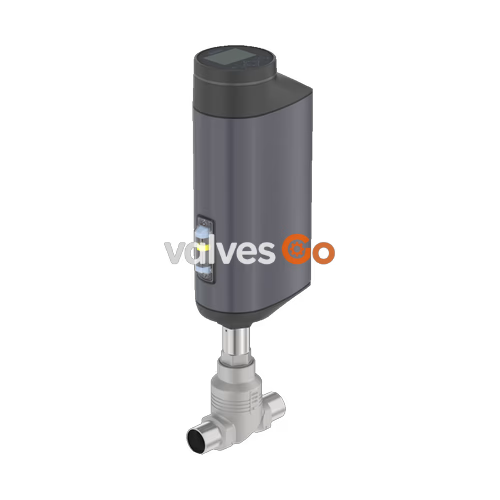
BURKERT 320767 (Type 3361) is an electromotive 2-way globe control valve with an AG2 linear actuator (nominal force 1,300 N), engineered for continuous control under demanding operating conditions. Article 320767 features a DN 20 port connection according to DIN 32676 series B for ISO 4200 pipe (26.9 x 1.6 mm, clamp flange diameter 50.5 mm) and a precision-cast stainless steel CF3M valve body. Fluid flows against the closing direction (flow below seat 2 → 1) with an equal-percentage flow characteristic and a 50:1 theoretical rangeability. The valve is driven by a 24 V DC brushless motor via a ball screw, delivering a positioning speed of 6 mm/s and a typical closing time of 3.3 seconds.
Sealing at the seat is stainless steel to stainless steel (1.4571) with leakage Class IV according to DIN EN 60534-4, operating across a medium temperature range from -10 °C to +185 °C and pressures from 0.00 to 25.00 bar(g). The unit includes an integrated position controller with a dead band of ±0.1%, an impact-resistant display module with operating keys, an optical 360° LED status ring, a mechanical position indicator, and a Service-büS interface for parameterization via Bürkert Communicator software.
| Specification Parameter | Value for Article 320767 |
|---|---|
| Product Type | Electromotive 2-way globe control valve |
| Burkert Type Family | 3361 |
| Actuator Size / Nominal Force | AG2 / 1,300 N |
| Nominal Diameter (Pipe Connection) | DN 20 (NPS 3/4") |
| Port Connection Type / Standard | Clamp connection / DIN 32676 series B (ISO 4200 pipe: 26.9 x 1.6 mm, Cl: 50.5 mm) |
| Flow Direction | Against closing direction (below seat, 2 → 1) |
| Nominal Pressure Rating | PN 25 (DIN EN 1333), Class 150 (DIN EN 1759) |
| Operating Pressure Range | 0.00 to 25.00 bar(g) |
| Flow Coefficient (Kvs) | 7.1 m³/h (water at +25 °C, DIN EN 60534-2-4) |
| Flow Coefficient (Cv) | 8.3 gpm |
| Seat Diameter | 20 mm (seat size 20) |
| Theoretical Rangeability | 50:1 |
| Flow Characteristic | Equal percentage |
| Seat Leakage Class | Class IV (DIN EN 60534-4) |
| Travel Speed | 6 mm/s (at 1,300 N actuator force) |
| Typical Closing Time | 3.3 s |
| Dead Band of Position Control | ±0.1% |
| Supply Voltage | 24 V DC ± 10% (max. residual ripple 10%) |
| Maximum Operating Current | 3 A (AG2 at maximum load) |
| Standby Power Consumption | 2 to 5 W |
| Duty Cycle | 100% continuous |
| Protection Class | Class III (DIN EN 61140) |
| Ingress Protection Rating | IP65 / IP67 (DIN EN 60529), NEMA 4X |
| Medium Temperature Range | -10 °C to +185 °C |
| Ambient Temperature Range | -25 °C to +65 °C (see derating limits) |
| Maximum Fluid Viscosity | Up to 600 mm²/s |
| Fail-Safe Position (Power Loss) | Blocking of static position, no electrical energy storage |
| Actuator Weight | Up to 5.5 kg (AG2 actuator alone) |
| Food Contact Compliance | (EC) 1935/2004 according to manufacturer declaration |
| Detergent Resistance | Ecolab certified (F&E/P3-E No. 40-1) |
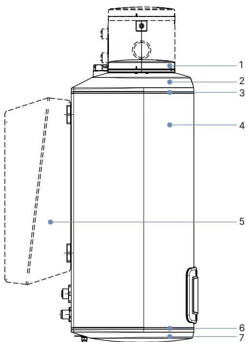
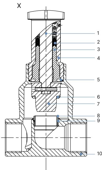
| Item | Component | Material |
|---|---|---|
| 1 | Display housing / blind cover | PPS (standard) |
| 2 | Actuator cover | PPS |
| 3 | Seal | EPDM |
| 4 | Actuator housing | Powder-coated aluminium |
| 6 | Seal | EPDM |
| 7 | Actuator base | PPS |
| — | Spindle | Stainless steel 1.4401 (316) / 1.4404 (316L) |
| — | Spindle seal | PTFE V-seals (filled) with spring compensation |
| — | Spindle guide | Stainless steel 1.4404 (316L) |
| — | Packing gland tube | Stainless steel 1.4401 (316) |
| — | Valve body seal | Graphite or PTFE |
| — | Valve seat seal | Stainless steel 1.4571 |
| — | Control cone | Stainless steel 1.4571 |
| — | Valve seat | Stainless steel 1.4571 |
| — | O-ring valve seat | EPDM or PTFE |
| — | Valve body | Stainless steel CF3M |
Type 3361 globe valves operate with fluid entering beneath the valve seat (flow direction 2 → 1). This configuration prevents pressure hammer during closing operations and supports high positioning stability across varied inlet pressures.
| Port Connection DN (NPS) | Seat Size | Actuator Force [N] | Max Operating Pressure [bar(g)] | Leakage Class | Theoretical Rangeability | Kv Value at Stroke: 5% | 10% | 20% | 30% | 40% | 50% | 60% | 70% | 80% | 90% | 100% (Kvs) |
|---|---|---|---|---|---|---|---|---|---|---|---|---|---|---|---|---|
| DN 20 (3/4") | 10 | 1,300 | 25 | IV | 50:1 | — | 0.12 | 0.16 | 0.20 | 0.33 | 0.52 | 0.77 | 1.2 | 1.8 | 2.6 | 3.2 m³/h |
| DN 20 (3/4") | 15 | 1,300 | 25 | IV | 50:1 | 0.14 | 0.17 | 0.22 | 0.35 | 0.52 | 0.80 | 1.2 | 1.8 | 2.9 | 4.0 | 5.2 m³/h |
| DN 20 (3/4") | 20 | 1,300 | 25 | IV | 50:1 | 0.20 | 0.25 | 0.30 | 0.45 | 0.70 | 1.1 | 1.6 | 2.4 | 3.5 | 5.2 | 7.1 m³/h |
INFO
Article 320767 is factory-fitted with seat size 20, providing a Kvs rating of 7.1 m³/h (Cv 8.3 gpm). The screwed-in seat ring design allows seat exchange to reduce orifice sizing if lower flow capacity or altered control spans are required on existing process lines.
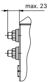
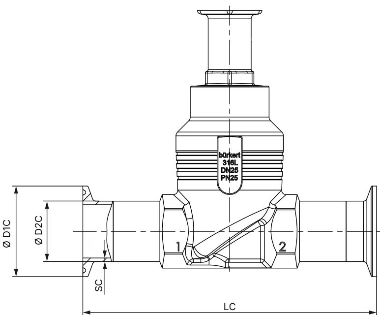
| Dimension Parameter | Dimension [mm] | Description |
|---|---|---|
| H1 | 423 mm | Total actuator height (in closed position, raised approx. 2 mm without sealing function) |
| LC | 136 mm | Face-to-face body length between clamp faces (DIN 32676 series B) |
| ∅ D2 C | 26.9 mm | Pipe outer diameter (DIN EN ISO 1127 / ISO 4200) |
| ∅ D1 C | 50.5 mm | Clamp flange outer diameter (DIN 32676 series B) |
| SC | 1.6 mm | Pipe wall thickness |
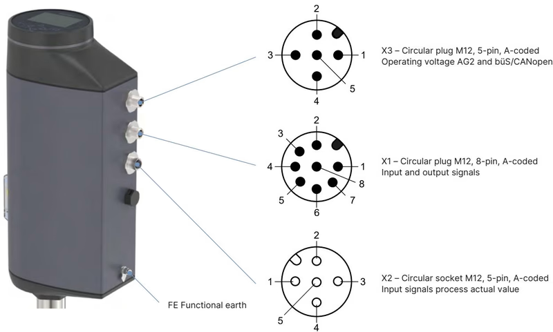
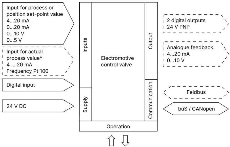
Article 320767 is configured with an analogue control interface utilizing M12 circular connectors on the AG2 actuator base.
| Connector Designation | Type and Coding | Function |
|---|---|---|
| X1 | M12 circular plug, 8-pin, A-coded | Input and output signals (analogue setpoint, binary input, analogue feedback, binary outputs) |
| X3 | M12 circular plug, 5-pin, A-coded | Operating voltage 24 V DC and büS/CANopen communication |
| Pin Number | Assignment | Technical Characteristics |
|---|---|---|
| 1 | Digital input + | 0 to 5 V = log "0", 10 to 30 V = log "1" |
| 2 | GND | Common reference for digital input and digital outputs |
| 3 | Digital output 2 + | PNP transistor output, max. current limitation 100 mA |
| 4 | Digital output 1 + | PNP transistor output, max. current limitation 100 mA |
| 5 | Analogue output - | Galvanically isolated feedback ground |
| 6 | Analogue output + | 0/4 to 20 mA (load 0 to 800 Ω) or 0 to 5/10 V (max. 10 mA) |
| 7 | Setpoint / Analogue input - | Galvanically isolated input ground |
| 8 | Setpoint / Analogue input + | 0/4 to 20 mA (input resistance 70 Ω) or 0 to 5/10 V (input resistance 22 kΩ) |
| Pin Number | Assignment | Details |
|---|---|---|
| 1 | CAN Shield / shield | Cable shield connection |
| 2 | Operating voltage + | 24 V DC ± 10% (max. ripple 10%) |
| 3 | GND / CAN_GND | Power supply ground and CAN reference |
| 4 | CAN_H | Bürkert system bus / CANopen dominant high line |
| 5 | CAN_L | Bürkert system bus / CANopen dominant low line |
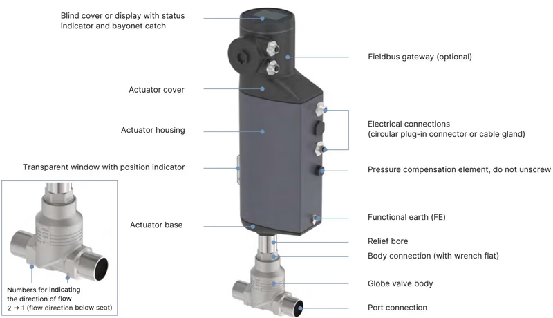
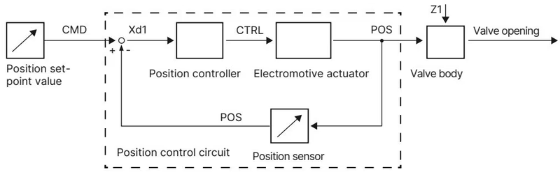
The internal microprocessor monitors the physical stroke through an integrated contactless linear displacement transducer (POS). The positioner compares the measured actual position with the setpoint value (CMD) received from the analogue input or digital bus. Any system deviation (Xd1) triggers the motor control electronics (CTRL), driving the brushless motor and ball screw to reposition the control cone until deviation is nullified within the ±0.1% dead band.
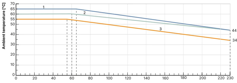
Permissible ambient temperature depends directly on the process fluid temperature. For AG2 actuators equipped with a display module, operating boundaries follow Curve 2 of the temperature limits chart:
Installation Position
The valve can be installed in any orientation. An upright vertical actuator orientation is recommended to reduce particulate deposition inside the packing gland.
Maintenance Safety Precautions
Depressurize and completely drain process lines before disassembling the actuator from the valve body. Ensure power is switched off. Do not actuate the mechanical manual override while power is connected to prevent drive mechanism damage.
| Mechanical Connection | Component Size | Tightening Torque |
|---|---|---|
| Valve body to body connection | DN 20 (NPS 3/4") | 50 ± 3 Nm |
| Valve seat ring | Seat size 20 (DN 20 body) | 28 + 3 Nm |
| Spindle guide (packing gland) | Spindle ∅ 10 mm (DN 20 body) | 25 Nm |
| Actuator base to housing screws | AG2 | 5 Nm |
| Mechanical manual override | 3 mm Allen socket | Max. 2 Nm |
Whenever the valve body is replaced, the actuator is remounted, or seat trim components are exchanged, run the automatic X.TUNE routine to calibrate end positions:
Explore similar products in our catalog


