Type 2032

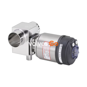
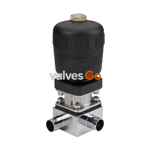
BURKERT 325395 (Type 2103) is a pneumatically operated 2/2-way diaphragm valve with stainless steel body, DN10 weld ends (DIN 11850 R1), normally closed CF A, EPDM seal, and 0–10 bar operating pressure.
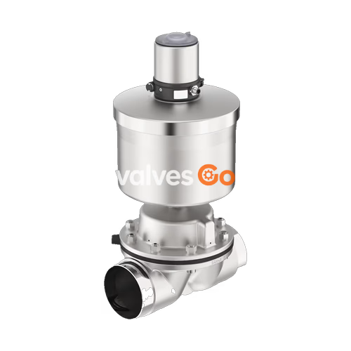
BURKERT 325395 (Type 2103) is a pneumatically operated 2/2-way diaphragm valve configured for decentralised automation in hygienic, sterile, and demanding industrial fluid applications. Assembled as a complete valve unit under article number 325395, this configuration features a forged stainless steel valve body with DN 10 weld ends conforming to DIN 11850 Series 1 (12 mm outer diameter, 10 mm inner diameter, 1.0 mm wall thickness) and a body nominal size of 8 mm (diaphragm size 8). The valve is actuated by a pneumatic piston drive with a polyphenylene sulphide (PPS) core protected by a 1.4561 (316Ti) stainless steel outer casing in actuator size 50 mm (D). Operating in Control Function A (normally closed by spring force), the valve controls line pressure from 0 bar to 10 bar using a pilot pressure range of 5.5 bar to 7.0 bar applied via a 6 mm ELEMENT interface push-in connection.
Sealing is performed by a high-temperature EPDM diaphragm rated for continuous medium temperatures from -10 °C to +143 °C, with steam sterilisation tolerance up to +150 °C for 60 minutes. The valve has a flow coefficient Kv of 1.0 m³/h for water and meets nominal pressure rating PN 16 (Class 150). With low dead volume, gap-free seals, and smooth exterior contours, the valve satisfies CIP and SIP requirements. The factory package includes a manufacturer inspection certificate 3.1 and a factory certification 2.1 for the membrane.
| Specification Parameter | Value / Range |
|---|---|
| Article Number | 325395 |
| Product Type | Type 2103 ELEMENT |
| Construction Status | Valve complete |
| Switching Positions | 2/2-way |
| Control Function | CF A (normally closed by spring force, NC) |
| Valve Piloting | Pneumatic |
| Nominal Diameter (Port Size) | DN 10 |
| Port 1 Connection Type | Weld end (DIN 11850 series 1 / R1) |
| Tube Dimensions | Inner Ø 10 mm, outer Ø 12 mm, wall thickness 1.0 mm |
| Diaphragm Size (Body Nominal Size) | 8 mm (Diaphragm size 8) |
| Flow Capacity Kv (Water) | 1.0 m³/h |
| Nominal Pressure Range | 0.00 bar to 10.00 bar |
| Pressure Rating Standards | PN 16 (DIN EN 1333) / Class 150 (DIN EN 1759) |
| Control / Pilot Pressure Range | 5.5 bar to 7.0 bar |
| Medium Temperature Range | -10 °C to +143 °C (steam sterilisation to +150 °C for 60 min) |
| Ambient Temperature Range | -10 °C to +55 °C (PPS actuator with push-in connector) |
| Valve Body Material | Forged stainless steel 1.4435 (BN2 / 316L) |
| Diaphragm Material | High-temperature EPDM (material code AD / E04) |
| Actuator Size | Ø 50 mm (D) |
| Actuator Housing Material | Polyphenylene sulphide (PPS) |
| Actuator Envelope / Casing | Stainless steel 1.4561 (316Ti) |
| Control Air Connection | ELEMENT interface, push-in fitting Ø 6 mm |
| Position Indicator | Without |
| Manual Override | No |
| Cleaning Capabilities | CIP capable, SIP capable |
| Quality Certifications | Test certificate 3.1, Membrane certification 2.1 |
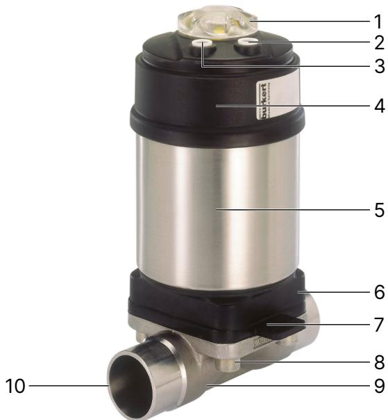
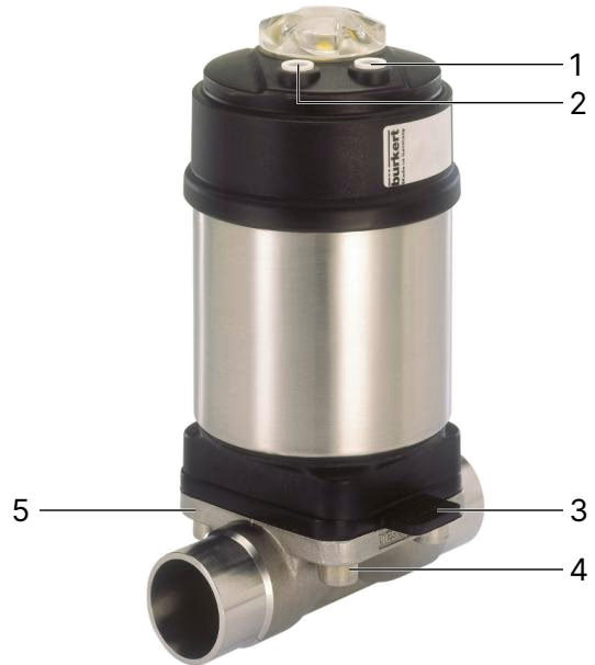
Type 2103 consists of a pneumatic piston actuator, an elastomer diaphragm, and a 2-way valve body. The piston mechanism transfers spring force or pneumatic thrust through a spindle to the compressor, pressing the diaphragm against the weir within the body.
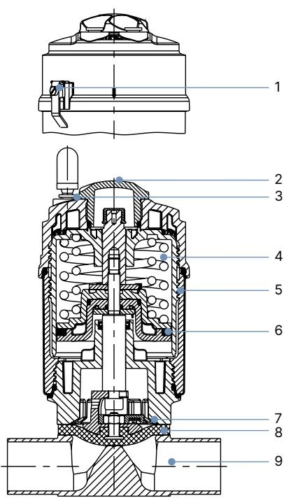
| Item No. | Component | Material |
|---|---|---|
| 1 | Ground terminal | Stainless steel 1.4301 / 1.4305 (ATEX/IECEx variant) |
| 2 | Transparent visual cap | Polysulfone (PSU) |
| 3 | Pilot air ports | Push-in connector PP (standard Ø 6 mm), G 1/8 stainless steel optional |
| 4 | Actuator core | Polyphenylene sulphide (PPS) |
| 5 | Actuator cover | Stainless steel 1.4561 (316Ti) |
| 6 | Piston seal | Fluoroelastomer (FKM) |
| 7 | Interface adapter | Polyphenylene sulphide (PPS standard), stainless steel 1.4308 optional |
| 8 | Diaphragm | EPDM high-temperature (AD) |
| 9 | Valve body | Forged stainless steel 1.4435 (BN2 / 316L) |
Food and Pharmaceutical Compliance
Diaphragms manufactured from EPDM (AD) comply with the United States FDA 21 CFR regulations, pass USP Class VI biological tests, and meet European Regulation (EC) No 1935/2004 for materials contacting food and beverages. Optional configurations conform to 3-A Sanitary Standards (code PE05) and TA-Luft air quality directives (code PM01).
Operating pressure ratings are determined by diaphragm material, body material, actuator size, and piloting pressure.
| Diaphragm Size | Actuator Size | Pilot Pressure | Body Material | Max Static Pressure (EPDM) | Max Dynamic Pressure (EPDM) |
|---|---|---|---|---|---|
| 8 | 50 (D) | 3.7 to 10 bar (nom. 5.5–7.0 bar) | All materials | 10 bar | 10 bar |
Permissible ambient temperature for the PPS actuator housing with push-in pneumatic connections is -10 °C to +55 °C (up to +60 °C depending on pneumatic piping type). Media temperatures must remain between -10 °C and +143 °C under standard operating conditions, with a temporary limit of +150 °C during clean-in-place steam sterilisation cycles of up to 60 minutes.
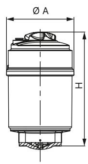
For diaphragm size 8 paired with actuator size 50 (D):
| Diaphragm Size | Actuator Size Ø | Actuator Cover Outer Ø A | Height H | Height H+M |
|---|---|---|---|---|
| 8 | 50 (D) | 65 mm | 119 mm | 141 mm |
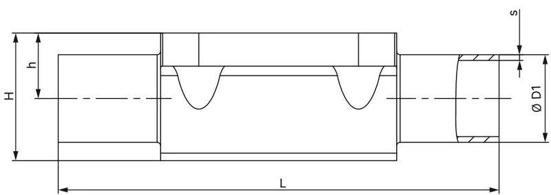
For diaphragm size 8, port connection DIN 11850 series 1 (tube dimensions 12.0 mm x 1.0 mm, port code SF40) and adjacent standards:
| Diaphragm Size | Port DN | Pipe Standard | Outer Ø D1 | Wall Thickness s | Length L | Dimension h | Dimension H | Product Key |
|---|---|---|---|---|---|---|---|---|
| 8 | 10 | DIN 11850 Series 1 | 12.0 mm | 1.0 mm | 90 mm | 9.3 mm | 18.8 mm | SF40 |
| 8 | 8 | DIN 11850 Series 0 | 10.0 mm | 1.0 mm | 90 mm | 5.7 mm | 15.2 mm | SC42 |
| 8 | 10 | DIN 11850 Series 2 | 13.0 mm | 1.5 mm | 90 mm | 9.3 mm | 18.8 mm | SD40 |
| 8 | 8 | DIN EN ISO 1127 | 13.5 mm | 1.6 mm | 90 mm | 9.3 mm | 18.8 mm | SA40 |
| 8 | 10 | DIN EN ISO 1127 | 17.2 mm | 1.6 mm | 90 mm | 9.3 mm | 18.8 mm | SA41 |
The valve may be installed in any orientation, preferably with the actuator facing upwards. When process piping requires complete emptying without pooling, the valve must be positioned according to specific self-draining criteria.
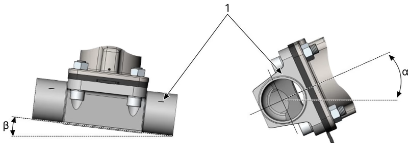
To establish self-draining performance:
| Port Connection Standard | Port Code | DN | Diaphragm Size | Pipe Dimension | Self-Draining Angle (α) |
|---|---|---|---|---|---|
| DIN 11850 Series 1 | SF40 | 10 | 8 | 12.0 x 1.0 mm | 24° |
| DIN 11850 Series 2 | SD40 | 10 | 8 | 13.0 x 1.5 mm | 24° |
| DIN 11850 Series 0 | SC42 | 8 | 8 | 10.0 x 1.0 mm | 39° |
| DIN EN ISO 1127 | SA41 | 10 | 8 | 17.2 x 1.6 mm | 13° |
Welding Precautions
Direct welding heat damages elastomer diaphragms and polymer actuator parts. For valves with welded port connections, the actuator and diaphragm must be unbolted and removed from the valve body before the body is welded into the pipe run.
| Diaphragm Size | Forged Body Torque: EPDM, FKM | Forged Body Torque: PTFE, GYLON® | Tube Body Torque: EPDM, FKM | Tube Body Torque: PTFE, GYLON® |
|---|---|---|---|---|
| 8 | 2.0 Nm (+10%) | 2.5 Nm (+10%) | 2.0 Nm (+10%) | 2.5 Nm (+10%) |
| 15 | 3.5 Nm (+10%) | 4.0 Nm (+10%) | 3.5 Nm (+10%) | 4.0 Nm (+10%) |
| 20 | 4.0 Nm (+10%) | 4.5 Nm (+10%) | 4.0 Nm (+10%) | 4.5 Nm (+10%) |
| 25 | 5.0 Nm (+10%) | 6.0 Nm (+10%) | 7.0 Nm (+10%) | 8.0 Nm (+10%) |
Article 325395 is supplied without an electrical position indicator. The modular ELEMENT actuator interface permits direct retrofitting of decentralized Bürkert automation units:
All ELEMENT control units mount without external tubing, routing pilot air internally to prevent environmental ingress and maintain IP65/67 protection.
The pneumatic actuator mechanism is maintenance-free under recommended operating parameters. Regular inspection is limited to seals and the diaphragm.
| Diaphragm Size | Diaphragm Material | Material Code | Spare Part Order Number |
|---|---|---|---|
| 8 | EPDM | E04 | 688421 |
| 8 | FKM | F01 | 677684 |
| 8 | PTFE / EPDM | L11 | 20093068 |
| 8 | Advanced PTFE | L12 | 20093078 |
| 8 | GYLON® / EPDM | L08 | 693175 |
Storage Recommendations
Elastomer spare parts should be stored in airtight packaging at temperatures between +5 °C and +25 °C, shielded from direct sunlight, ozone sources, and relative humidity exceeding 65%. Under these conditions, the maximum storage shelf life for EPDM diaphragms is 7 years with an anticipated operational service life of up to 3 years.
Explore similar products in our catalog