Skip to content
Servo-assistedNormally Closed (NC)IP65

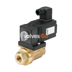
BURKERT 325978 Type 6407 Servo-Assisted 2/2-Way Piston Valve

BURKERT 325978 Type 6407 servo-assisted 2/2-way piston valve. Features G 3/4 internal thread, 20mm orifice, brass body, PTFE seals, and 0-10 bar pressure range.
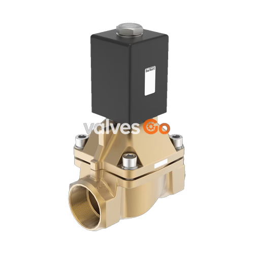
BURKERT 325978 Type 6407 Servo-Assisted 2/2-Way Piston Valve

BURKERT 325978 Type 6407 is a servo-assisted 2/2-way piston valve. The fixed coupling between the pilot valve and the piston provides an opening of the valve without a pressure difference. As a piston valve, the Type 6407 is particularly suitable for media such as gas and steam, as well as liquids with low operating temperatures below 0 °C. The stopper and the core guide pipe are welded together to enhance pressure resistance and leak-tightness. The coils are moulded with chemically resistant epoxy. In combination with a plug according to DIN EN 175301-803 Form A, the valve satisfies the IP65 degree of protection.
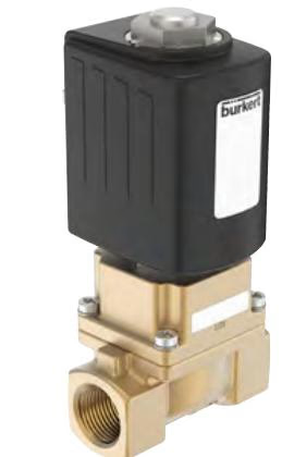
BURKERT 325978 Type 6407 servo-assisted 2/2-way piston valve

Key Features

  • Servo-assisted piston valve up to DN 50 orifice (Model 325978 is DN 20)
  • Safe opening with hard-coupled piston system without differential pressure
  • Vibration-resistant, push-over coil system
  • Suitable for neutral gases and liquids (e.g., compressed air, water, hydraulic oil, hot water, and steam)

Circuit Function

Circuit function A (CF A): 2/2-way solenoid valve, servo-controlled, normally closed.
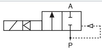
BURKERT 325978 Type 6407 circuit function A normally closed

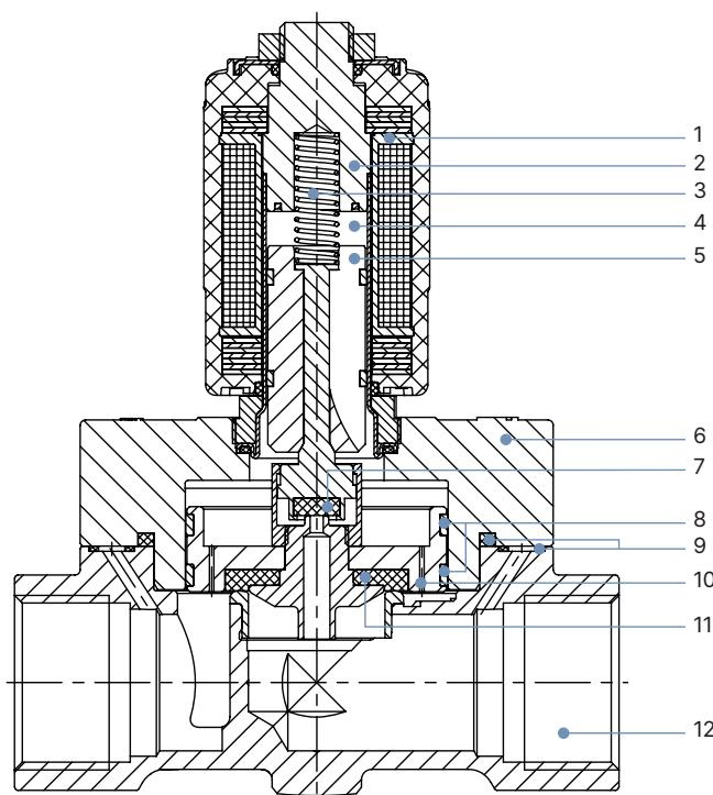
Material Specifications

BURKERT 325978 Type 6407 threaded body material specifications

No.ElementMaterial
1CoilEpoxy
2StopperStainless steel 1.4113/434
3SpringStainless steel 1.4310/301
4Armature guide tubeStainless steel 1.4303/305/308
5CoreStainless steel 1.4113/434
6CoverBrass
7SealPTFE
8Piston ringPTFE
9Sealing ringGraphite
10PlungerBrass
11Piston sealPTFE
12BodyBrass

Dimensions

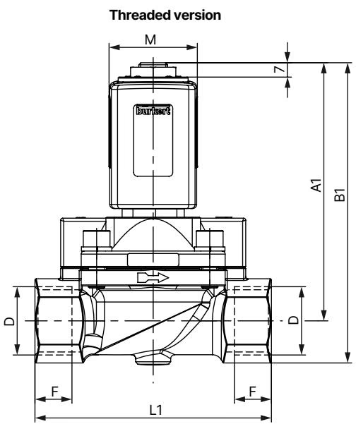
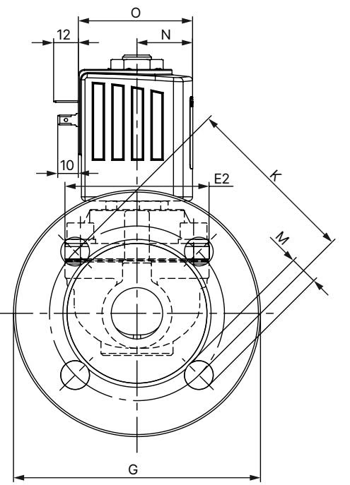
Standard variant DN 13…DN 32

BURKERT 325978 Type 6407 dimensions drawing for threaded variant

BURKERT 325978 Type 6407 dimensions table for standard variant

Note

  • Dimensions in mm
  • The dimensions D1 and F1 apply to G thread.
  • The dimensions D2 and F2 apply to NPT thread.
  • The dimensions D3 and F3 apply to Rc thread.

Safety and Installation

Risk of injury from high pressure and escaping medium

  • Switch off the pressure before working on the device or system. Vent or drain the lines.

Risk of injury from electric shock

  • Switch off the power supply before working on the device or system. Secure against reactivation.
  • Observe the applicable accident prevention and safety regulations for electrical devices.

Risk of injury due to improper installation

  • Installation must always be carried out by trained technicians with the appropriate tools.
  • Secure the system against unintentional activation.
  • Ensure a controlled restart after installation.

Before installation:

  • Installation position: any, preferably actuator facing up.
  • Clean pipelines of dirt.
  • Install a dirt trap upstream of the valve inlet (≤ 500 µm).

Installation:

  • Hold the device on the body using an appropriate tool (e.g. open-end wrench) and screw into the pipeline.
  • The valve body must not be installed under tension. Seal material must not get into the device.
  • Observe the flow direction: the arrow on the body indicates the flow direction.