PN16

Bürkert Type 6213 servo-assisted 2/2-way diaphragm valve. Features a spring-coupled diaphragm for opening without differential pressure, high flow rate, and optional Kick and Drop coil.
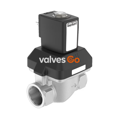
Bürkert Type 6213 is a servo-assisted diaphragm valve with a nominal diameter of up to DN 40. The spring coupling of the diaphragm supports the opening process in the valve. In its standard variant, the valve is suitable for deployment with liquids. A minimum differential pressure is required for full opening. For gas and vacuum applications, a special variant is available (HP00) that opens the valve without differential pressure. Various diaphragm materials are available depending on the actual application. The body is available in brass, stainless steel, and gunmetal. For other markets, dezincification-resistant brass is available. To reduce electrical power consumption during operation, coils with integrated Kick-and-Drop (KD) electronics featuring double coil technology are available.
| Product properties | |
|---|---|
| Dimensions | See Dimensions section |
| Material | |
| Seal | NBR, FKM, EPDM |
| Body | Brass acc. to DIN EN 50930-6, Stainless steel 1.4408, Gunmetal (external thread) DN 10...DN 20 |
| Coil | Polyamide, epoxy (insulation class H) |
| Valve inner parts | Brass body: brass, stainless steel and PPS Stainless steel body: stainless steel and PPS Gunmetal body: stainless steel and PPS (external thread) DN 10...DN 20 |
| Orifice | Standard: DN 10...DN 40 HP00: DN 13...DN 20 |
| Circuit function | A (2/2-way solenoid valve, Servo-controlled, Normally closed) |
| Thermal insulation class | Epoxy coil class H |
| Performance data | |
| Duty cycle | 100 % continuous operation; KD coil max. 6 switching cycles/minute |
| Switching time AC/DC | DN 10...13: Opening 10...100 ms, Closing 100...200 ms DN 20: Opening 200...300 ms, Closing 400...700 ms DN 25...40: Opening 300...400 ms, Closing 800...1400 ms |
| Electrical data | |
| Operating voltage | Standard: 24 V DC, 24 V 50 Hz, 230 V 50 Hz, 110 V 50 Hz, 120 V 60 Hz HP00: 24 V DC, 24 V 50/60 Hz, 230 V 50/60 Hz |
| Voltage tolerance | ±10% |
| Medium data | |
| Operating medium | Medium that does not attack the housing and sealing materials |
| Medium temperature | With NBR: -10 °C...+80 °C With FKM: 0 °C...+90 °C (polyamide coil), 0 °C...+120 °C (epoxy coil) With EPDM: -30 °C...+90 °C (polyamide coil), -30 °C...+100 °C (epoxy coil) |
| Viscosity | Max. 21 mm²/s |
| Product connections | |
| Port connection | G, NPT, Rc (1/4 to 2) |
| Environment and installation | |
| Installation | As required, preferably with actuator upright |
| Ambient temperature | Standard variant: Max. + 55 °C AC10 (10 switching cycles/min): Max. + 70 °C AC19 (10 switching cycles/min): Max. + 70 °C |
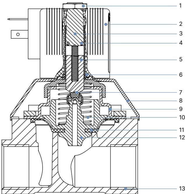
| No. | Element | Material |
|---|---|---|
| 1 | Nut | Steel (thick-film passivated according to RoHS), Stainless steel 1.4305, PTFE-coated |
| 2 | Coil | Polyamide or epoxy |
| 3 | Stopper | Stainless steel 1.4113 |
| 4 | Shading ring (only AC) | with brass body: copper (Cu) with stainless steel body: silver (Ag) |
| 5 | Magnetic core | Stainless steel 1.4113 |
| 6 | O-ring | FKM |
| 7 | Plunger seal | NBR, FKM, EPDM |
| 8 | Bonnet | PA6 |
| 9 | Cover | DN 10...25: stainless steel 1.4301 DN 40: brass, stainless steel 1.4408 |
| 10 | Spring | Stainless steel 1.4310 |
| 11 | Diaphragm | NBR, FKM, EPDM |
| 12 | Diaphragm support | PPSGF40 in combination with brass and accordingly stainless steel parts |
| 13 | Valve body | Brass, stainless steel 1.4408, Gunmetal with external thread |
| DN | A | B | C | D | E | G1 | NPT G2 | Rc G3 | L | SW | Coil size |
|---|---|---|---|---|---|---|---|---|---|---|---|
| 10 | 71.1 | 82.1 | 36 | 46 | 22 | G 1/4 | NPT 1/4 | - | 50 | 22 | 5 and 6 |
| 10 | 71.1 | 82.1 | 36 | 46 | 22 | G 3/8 | NPT 3/8 | Rc 3/8 | 50 | 22 | 5 and 6 |
| 10 | 73.1 | 86.6 | 24.5 | 14 | 24.5 | G 1/2 | NPT 1/2 | Rc 1/2 | 50 | 27 | 5 and 6 |
| 13 | 82.6 | 95.9 | 44.5 | 56.7 | 27.25 | G 1/2 | NPT 1/2 | Rc 1/2 | 58 | 27 | 5 and 6 |
| 13 | 84.6 | 100.6 | 32.5 | 16 | 32.5 | G 3/4 | NPT 3/4 | Rc 3/4 | 65 | 32 | 5 and 6 |
| 20 | 97.1 | 113.1 | 65 | 76.6 | 37 | G 3/4 | NPT 3/4 | Rc 3/4 | 80 | 32 | 5 and 6 |
| 20 | 99.6 | 120.1 | 37.5 | 18 | 37.5 | G 1 | NPT 1 | Rc 1 | 80 | 41 | 5 and 6 |
| 25 | 143.4 | 163.4 | 77 | 88 | 46 | G 1 | NPT 1 | Rc 1 | 95 | 41 | K and L |
| 25 | 148.3 | 173.3 | 46 | 20 | 46 | G 1 1/4 | NPT 1 1/4 | Rc 1 1/4 | 95 | 50 | K and L |
| 40 | 153.9 | 178.9 | 104.5 | 117 | 61 | G 1 1/4 | NPT 1 1/4 | Rc 1 1/4 | 126 | 50 | K and L |
| 40 | 159.4 | 189.4 | 61 | 22 | 61 | G 1 1/2 | NPT 1 1/2 | Rc 1 1/2 | 126 | 60 | K and L |
| 40 | 165.4 | 200.4 | 64 | 24 | 64 | G 2 | NPT 2 | Rc 2 | 132 | 70 | K and L |
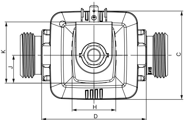
| DN | A | B | C | D | G | L | SW | Coil size |
|---|---|---|---|---|---|---|---|---|
| 10 | 73.1 | 86.1 | 36 | 46 | G 1/2 | 80 | 26 | 5 and 6 |
| 13 | 84.6 | 100.6 | 44.5 | 56.7 | G 3/4 | 89 | 32 | 5 and 6 |
| 20 | 99.6 | 118.5 | 65 | 76.6 | G 1 | 108 | 37.7 | 5 and 6 |
| 13 | 104.3 | 120.3 | 44.5 | 56.7 | G 3/4 | 89 | 32 | K and L |
| 20 | 119.3 | 139.8 | 36 | 76.6 | G 1 | 108 | 37.7 | K and L |
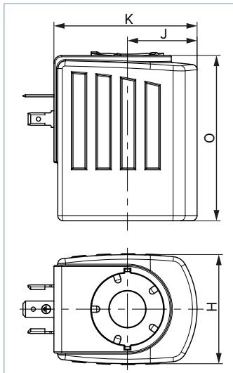
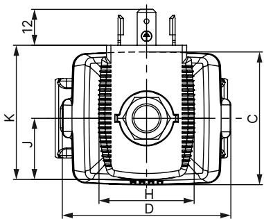
| Coil size | H | J | K | O | M |
|---|---|---|---|---|---|
| 5 | 32 | 20.5 | 45 | 41 | 3.4 |
| 6 | 40 | 23.5 | 51 | 41 | 3.4 |
| K | 42 | 27 | 55.5 | 64 | 7 |
| L | 65 | 37.5 | 72 | 64 | 7 |
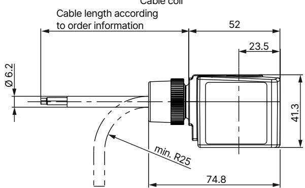
| Nominal size [mm] | Coil size [mm] | AC Inrush [VA] | AC Holding [VA] | AC Cold [W] | DC Warm [W] | DC Nominal [W] | AC/DC ATEX [W] |
|---|---|---|---|---|---|---|---|
| 10 | 32 | 34 | 14 | 8 | - | - | - |
| 10 | 40 | - | - | 10 | 11 | 10 | 9 |
| 13 | 32 | 36 | 14 | 8 | - | - | - |
| 13 | 40 | - | - | 10 | 11 | 10 | 9 |
| 13 | 42 | 125 | 37 | 16 | 21 | 16 | - |
| 20 | 32 | 38 | 14 | 8 | - | - | - |
| 20 | 40 | - | - | 10 | 11 | 10 | 9 |
| 20 | 42 | 140 | 37 | 16 | 21 | 16 | - |
| 25 | 42 | 150 | 37 | 16 | - | - | - |
| 25 | 65 | - | - | - | 28 | 21 | - |
| 40 | 42 | 190 | 37 | 16 | - | - | - |
| 40 | 65 | - | - | - | 28 | 21 | - |
| Nominal size [mm] | Coil size [mm] | Cold power Inrush (500 ms) [W] | Cold power Holding [W] | Warm power Holding [W] |
|---|---|---|---|---|
| 10...13 | 40 | 20 | 2 | - |
| 13...20 | 42 | 44 | 6.5 | 5.5 |
| 13...20 | 42 (ATEX) | 44 | 6.5 | 5.5 |
| 13...40 | 42 | 85 | 8.5 | 7 |
DANGER!
Risk of injury from high pressure in the system Before loosening lines or valves, switch off the pressure and vent the lines. Risk of injury from electric shock Before reaching into the device or the system, switch off the power supply and secure it against reactivation.
To manually operate the valve, the hand lever must be turned to a vertical position below the solenoid. Do not over-rotate the hand lever. When the hand lever is actuated, the valve can no longer be switched electrically.

WARNING!
Overheating, risk of fire Connecting the solenoid without a pre-installed valve will cause overheating and destroy the solenoid. Only connect the solenoid after the valve has been installed.
Explore similar products in our catalog