


Up to 99.8% Efficiency

BURKERT 339924 Type 2300 is a pneumatic 2-way stainless steel angle seat control valve DN25 with weld ends, equal percentage trim (50:1), 0-12 bar operating range, and PTFE seal for liquid and steam service.
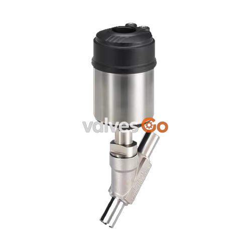
BURKERT 339924 (Type 2300) is a 2-way pneumatically operated angle seat control valve designed for precise throttling in demanding industrial media loops. Built as a complete valve assembly, it features a stainless steel body with DN 25 weld end process connections complying with DIN 11850 R2 and DIN 11866 Series A (outer diameter 29 mm, inner diameter 26 mm, wall thickness 1.5 mm). Flow enters below the seat across a 25 mm seat orifice, regulated by an equal percentage control cone providing a 50:1 turndown ratio and a water flow capacity of Kv 16 m³/h. Operating under control function A (normally closed by spring force), the valve controls fluid media across a working pressure range of 0 bar to 12 bar (rated PN 25 and Class 150) using pilot pneumatic pressure between 5.5 bar and 7 bar via an ELEMENT 6 mm pilot air port.
Engineered for hygienic and clean-utility processes, the valve body and PTFE seat seal provide complete CIP (clean-in-place) and SIP (steam-in-place) capability. Materials meet European Regulation (EC) 1935/2004 and FDA food contact requirements according to manufacturer declarations. Fluid operating temperatures range from -10 °C to +130 °C, and ambient environmental temperatures extend from -10 °C to +100 °C. The valve actuator housing is constructed from PPS (polyphenylene sulphide) without an integrated position indicator, manual override, vacuum execution, or oxygen-specific degreasing.
| Specification Parameter | Value |
|---|---|
| Burkert Type / Part Identifier | Type 2300 / 339924 |
| Valve Construction | Complete 2-way angle seat control valve |
| Control Function | A: Normally closed (NC) |
| Nominal Diameter (DN) / Seat Diameter | DN 25 / 25 mm |
| Port 1 Connection Type | Weld end |
| Connection Pipe Standards | DIN 11850 R2, DIN 11866 Series A |
| Connection Pipe Dimensions | Outer Ø 29 mm, Inner Ø 26 mm, Wall thickness 1.5 mm |
| Valve Body Material | Stainless steel |
| Seat Seal Material | PTFE (Polytetrafluoroethylene) |
| Actuator Material | PPS (Polyphenylene sulphide) |
| Flow Direction | Below seat |
| Control Cone Variant | Equal percentage 50:1 |
| Flow Capacity Kv (Water) | 16 m³/h |
| Process Operating Pressure Range | 0.00 bar to 12.00 bar |
| Nominal Pressure Class | PN 25 (DIN EN 1333) / Class 150 (DIN EN 1759) |
| Pneumatic Pilot Pressure | 5.5 bar to 7.0 bar |
| Pilot Air Port Interface | Interface ELEMENT, 6 mm diameter |
| Medium Temperature Range | -10 °C to +130 °C |
| Ambient Temperature Range | -10 °C to +100 °C |
| Hygienic Conformity | CIP capable, SIP capable, EC 1935/2004, FDA compliant |
| Manual Override / Position Indicator | No / Without |
| Inspection Certificate | Manufacturer's test certificate 3.1 not enclosed |
When equipped with supplementary code PX51, the mechanical actuator assembly complies with certification EPS 18 ATEX 2 008 X and IECEx EPS 18.0007 X (mech. Ex h IIC T4…T2 Gb / Ex h IIIC T135 °C…T300 °C Db). It is categorized as Category 2 non-electrical mechanical equipment with structural safety for application in Zone 1 / Zone 21 and Zone 2 / Zone 22.
Explosion Hazard
Installation, operation, and maintenance must only be performed by qualified technical personnel using appropriate tools. Operate the equipment only when undamaged and in strict compliance with the operating manual. Observe applicable national safety regulations and general technical installation practices. Repairs must be carried out solely by the manufacturer; do not repair defective units independently. Never place external mechanical loads on the valve body or actuator.
Surface and medium temperatures are restricted depending on the classified temperature grade. Note that the standard non-Ex operating envelope (-10 °C to +130 °C medium, -10 °C to +100 °C ambient) further restricts the maximum operating limits of this valve assembly.
| Temperature Class | Permissible Surface Temperature | Ambient Temperature Range | Maximum Medium Temperature |
|---|---|---|---|
| T2 | 300 °C | -40 °C to +130 °C | 285 °C |
| T3 | 200 °C | -40 °C to +130 °C | 185 °C |
| T4 | 135 °C | -40 °C to +100 °C | 125 °C |
Sudden electrostatic discharge from charged components or personnel creates an ignition risk in hazardous atmospheres. Observe the following operational precautions:

Marking Validity
The ATEX/IECEx marking label identifies structural safety under certified atmospheric conditions. If auxiliary equipment or accessories lacking hazardous area authorization are mounted to the valve assembly, the explosion protection marking becomes invalid.
Flammable and Explosive Media
Conveying explosive or combustible media introduces additional ignition risks that require plant-level hazard evaluation. When cleaning equipment located inside hazardous areas, use only cleaning agents formally certified and permitted for explosive atmospheres.
Control units mounted onto the actuator may introduce separate environmental limitations. Always consult the specific control unit operating instructions.
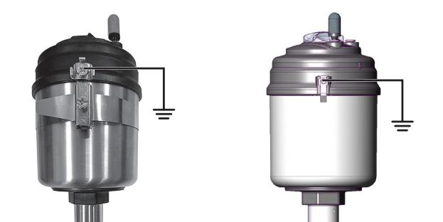
Conductive components must be integrated into the site potential equalization (PA) network:
Explore similar products in our catalog


