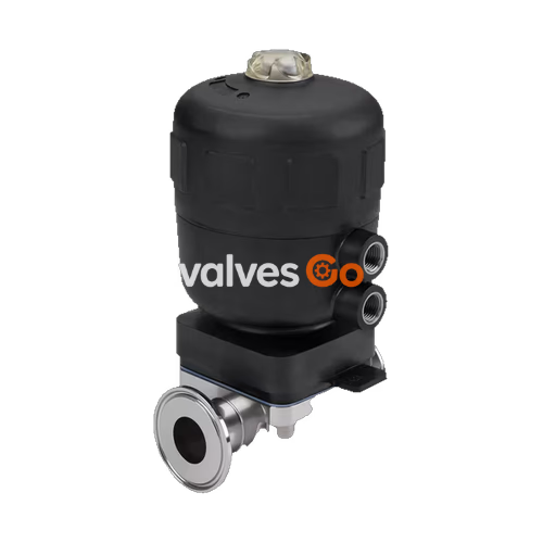
Burkert 342185 Type 2031 is a 2/2-way piston-operated diaphragm valve equipped with a 63mm pneumatic PPS plastic actuator. It uses neutral gases or air to control the flow of media and is designed for highly purified, sterile, aggressive, or abrasive media. The valve features a forged stainless steel body, an EPDM seal (food quality), and an ASME BPE clamp connection. It is self-draining when installed in the appropriate position.
Product Overview
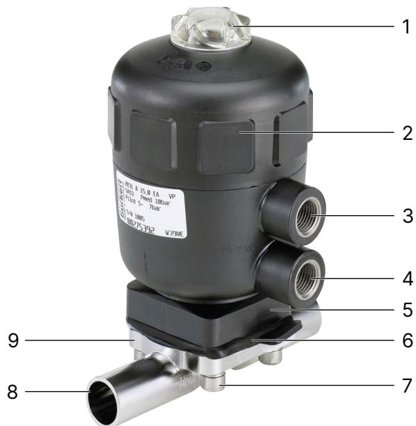
The externally controlled diaphragm valve consists of a pneumatically operated piston actuator, a diaphragm seal, and a 2-way valve body.
Product Identification
Functionality
Depending on the control function, spring force or pneumatic pilot pressure generates the closing force. A spindle connected to the actuator piston transfers the force to the compressor, which presses the diaphragm against the weir in the valve body.
This specific model (342185) operates with Control function A (CF A): Pneumatically operated 2/2-way on/off valve, bidirectional, closed by spring force in rest position.
Technical Data
Operating Conditions
- Medium: Neutral gases and liquids, ultrapure, sterile, aggressive or abrasive media.
- Control medium: Neutral gases, air.
- Ambient temperature (PPS actuator ≤80): +5...+140 °C
- Medium temperature (EPDM diaphragm): -10...+143 °C (Steam sterilisation max. +150 °C for 60 min)
Risk of bursting due to overpressure
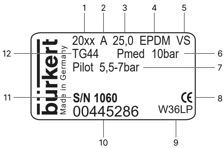
If the device bursts, escaping media may cause injuries, burns or scalds. Do not exceed the maximum permissible pilot pressure or maximum permissible operating pressure. Observe specifications on the type label.
Pressure Specifications (Control Function A)
For diaphragm size 20 and actuator size 63 (E):
- Pilot pressure: 5.5–7 bar
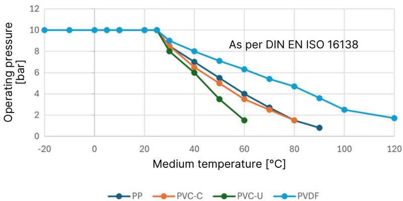
- Maximum operating pressure (EPDM): 10 bar (Dynamic), 10 bar (Static)
Installation
Ensuring Self-Draining
The installer and the operator are responsible for ensuring self-draining.
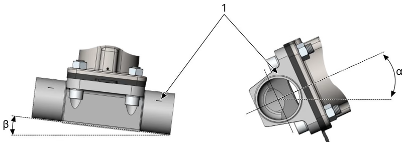
- Inclination angle of the pipeline: The inclination angle is determined by the installer or operator. For pipelines, the inclination angles specified in the valid ASME BPE standard are recommended.
- Self-draining angle for valve body: The marking for self-draining angles on the port connection serves as a guide and must point upwards. The actual angle must be set with a suitable measuring tool.
Installing the Actuator on the Valve Body (CF A)
- Ensure the correct position of the compressor.
- Pressurise the lower pilot air port with compressed air (value as indicated on the type label): valve opens.
- Place the actuator together with the diaphragm on the valve body.
- Slightly tighten the body screws crosswise until the diaphragm rests between the valve body and the actuator. Do not fully tighten the screws yet.
- Actuate the valve twice to position the diaphragm correctly.
- Switch off the pilot pressure.
- Without applying pressure, tighten the body screws in three stages (approx. 1/3, then 2/3 and then full tightening torque), in each case crosswise. The diaphragm should be positioned and pressed evenly all around the actuator and valve body.
Tightening torque for Diaphragm Size 20 (EPDM): 4 Nm.
Maintenance
The device actuator is maintenance-free if the instructions in the operating manual are followed. Components which are subject to natural wear are seals and the diaphragm.
- Inspection intervals: After the first steam sterilisation and when required, tighten the body screws crosswise. After $10^5$ switching cycles at the latest, check the diaphragm for wear. Shortened inspection intervals are required for muddy and abrasive media.
- Leakage detection: The relief bore must be inspected at regular intervals for any medium leakages. A bulging diaphragm may reduce the flow rate.